Impingement Cooling Structures for Gas Turbines

A cooling structure, gas turbine technology, applied in the cooling of the engine, the cooling of the turbine/propulsion device, the mechanical equipment, etc., can solve the problem of reducing the effect of the impact cooling effect, etc., to reduce the impact, enhance the cooling effect, and reduce the gas The effect of lateral flow

Active Publication Date: 2017-06-09
AECC COMML AIRCRAFT ENGINE CO LTD
View PDF7 Cites 0 Cited by
  • Summary
  • Abstract
  • Description
  • Claims
  • Application Information

AI Technical Summary

Problems solved by technology

However, this design cannot solve the effect of reducing the impact cooling effect of the cross flow in the impingement channel between the insert and the turbine blade

Method used


Image

  • Impingement Cooling Structures for Gas Turbines
  • Impingement Cooling Structures for Gas Turbines
  • Impingement Cooling Structures for Gas Turbines

Examples


Embodiment Construction

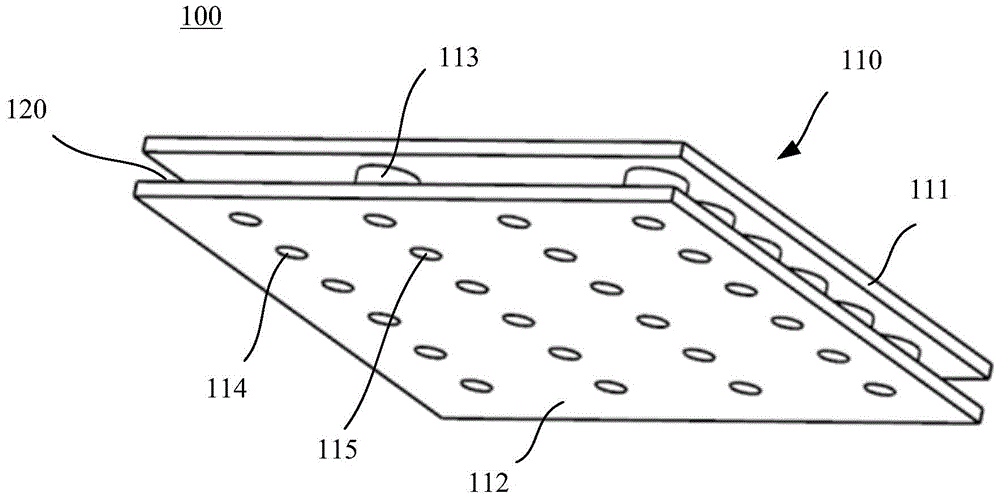
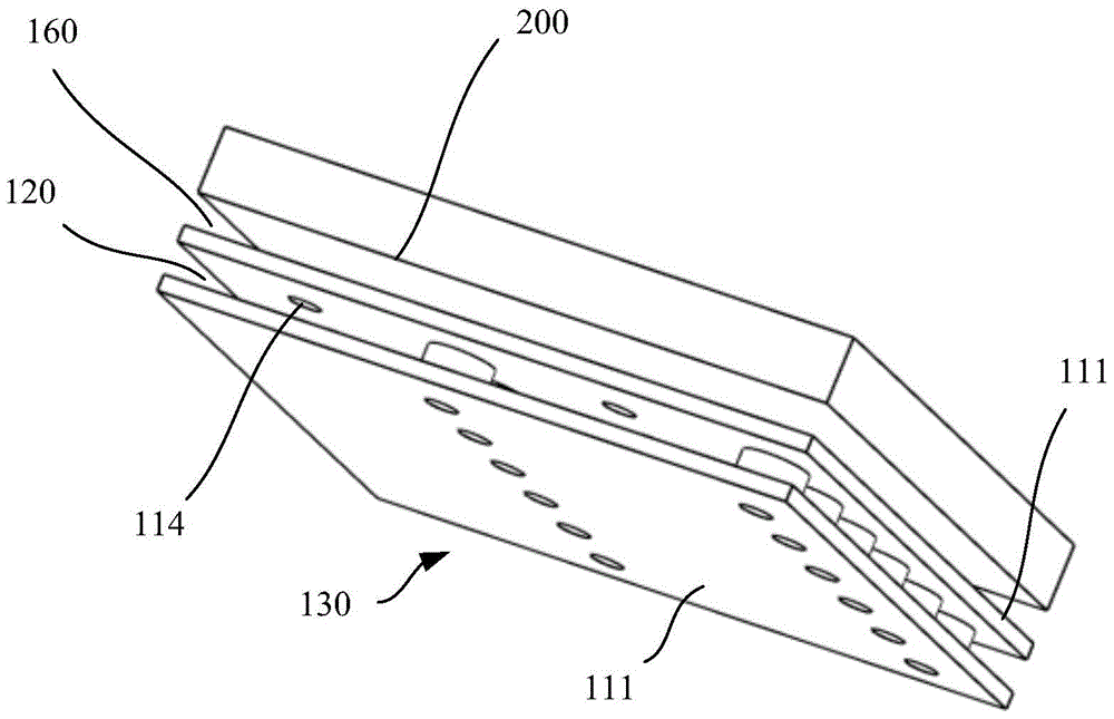
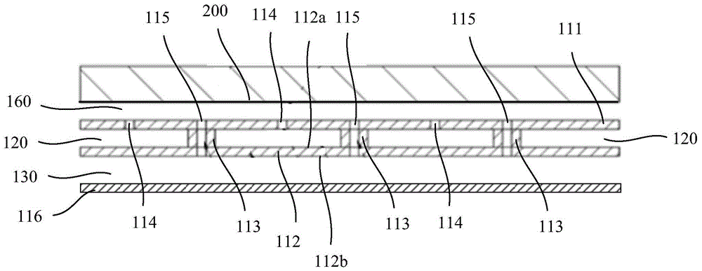
[0024] figure 1 A perspective view showing an impingement cooling structure according to an embodiment of the present invention. figure 2 A schematic diagram of cooperation between the impingement cooling structure and the wall to be cooled according to an embodiment of the present invention is shown. image 3 A schematic cross-sectional view showing an impingement cooling structure according to an embodiment of the present invention. refer to Figure 1-3 As shown, an impingement cooling structure 100 for a gas turbine in this embodiment includes an impingement bushing 110 , a gas outlet 114 , a gas return port 115 , a gas introduction area 120 , and a gas outlet area 130 . The impact bushing 110 is spaced opposite to the wall surface 200 to be cooled, forming an impact channel 160 . Here, the wall to be cooled may be the middle wall of the turbine blade or the wall of the combustion chamber. A plurality of gas outlets 114 are distributed over the impingement liner 110 an...


PUM


Abstract

The invention relates to an impingement cooling structure for a gas turbine, comprising an impingement bushing, multiple gas outlets, multiple gas return ports, a gas introduction area and a gas export area. The impact bush is spaced opposite to the wall to be cooled to form an impact channel. The plurality of gas outlets are disposed on the impingement bushing and face the impingement channel. The plurality of gas return ports are disposed on the impact bushing and face the impact channel. The gas introduction area communicates with each gas outlet. The gas outlet area is isolated from the gas introduction area and communicated with each gas return port. The pressure of the gas introduction area is higher than the pressure of the impact area, and the pressure of the impact area is higher than the pressure of the gas outlet area.

Description

technical field [0001] The invention relates to the field of gas turbine engines (gas turbines for short), in particular to an impingement cooling structure for gas turbines. Background technique [0002] In gas turbine engines used in aviation or industry, the surface of the turbine blades of the gas turbine will be exposed to high temperature gas during operation. In order to prevent the overheating of the turbine blades and ensure the long-term safe and reliable operation of the turbine blades, it is necessary to cool the turbine blades to reduce the temperature of the blades, and at the same time reduce the temperature difference of the blades as much as possible and reduce the thermal stress of the blades. [0003] As an efficient cooling technology, impingement cooling is widely used in the cooling of turbine blades and combustion chamber walls of gas turbines. The basic principle of impact cooling is that the cooling air flows out through the impact hole and hits the...

Claims


Application Information

Patent Timeline
Patent Type & Authority Patents(China)
IPC IPC(8): F02C7/12F01D5/18
Inventor 王辉罗昌金王克菲王晓增冯晓星
Owner AECC COMML AIRCRAFT ENGINE CO LTD
Why Eureka
Try Eureka