Electrolytic machining technique and device for small bore diameter inner wall surface fine groove

A processing technology and processing device technology, applied in the field of electrolytic processing technology and devices, can solve the problems of low processing efficiency and forming precision, difficult tool electrode preparation, unstable processing process, etc., and achieve good curing performance, easy process, and solidification fast effect

Inactive Publication Date: 2008-09-10
ZHEJIANG UNIV OF TECH
View PDF3 Cites 22 Cited by
  • Summary
  • Abstract
  • Description
  • Claims
  • Application Information

AI Technical Summary

Problems solved by technology

[0006] The technical problem to be solved by the present invention is to provide an electrolytic machining process and device for fine grooves on the inner wall surface of a small aperture, so as to solve the difficulties in the preparation of tool electrodes for machining small-sized variable-section holes, large processing apertures, and easy peeling of photoresist. Unstable processing, low processing efficiency and low forming accuracy

Method used


Image

  • Electrolytic machining technique and device for small bore diameter inner wall surface fine groove
  • Electrolytic machining technique and device for small bore diameter inner wall surface fine groove
  • Electrolytic machining technique and device for small bore diameter inner wall surface fine groove

Examples


Embodiment 1

[0034] Embodiment 1 (annular groove)

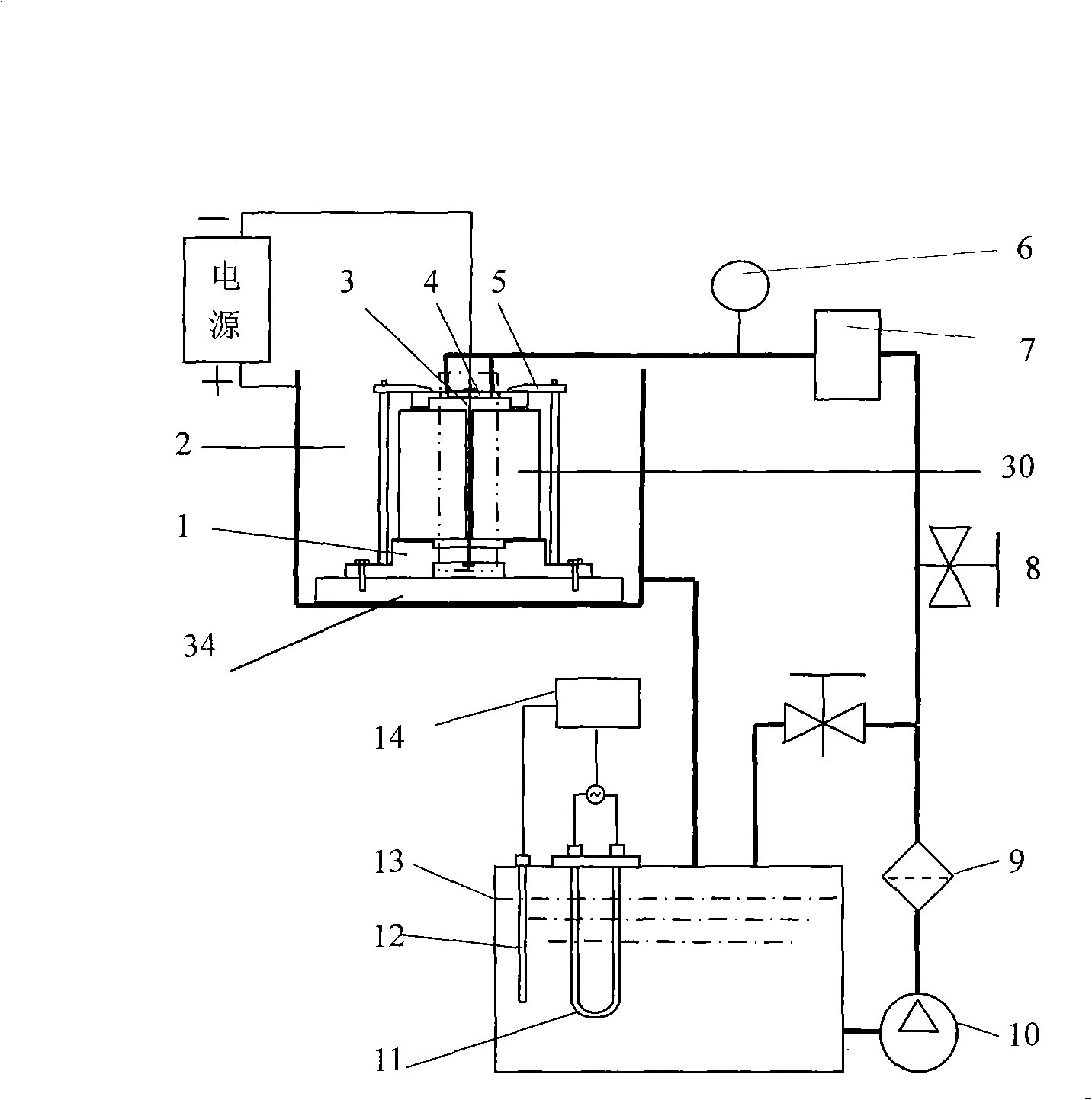
[0035] Such as figure 1 Shown, a kind of electrolytic processing device of micro-groove on the wall surface of small aperture, electrolytic processing device comprises electrolytic cell, electrolyte storage tank and the power supply that is electrically connected with electrolytic cell, described electrolyte storage tank is connected with vacuum pump and circulating pipeline. The electrolytic cell is circulated, and the electrolytic cell includes a processing chamber 2, a base 34 fixed on the bottom of the processing chamber 2, an upper cover plate 4 for fixing a prefabricated workpiece 30 with a light hole, a lower cover plate 1 and a clamp 5. The lower cover plate 1 is fixed on the base, the clamp is connected to the lower cover plate 1, the upper cover plate 4 and the prefabricated workpiece with light holes pass through the pressing plate of the clamp 5 and the lower cover plate 1 Fixing, the upper cover plate 4 and the lower cover p...

Embodiment 2

[0044] Embodiment 2 (spiral groove)

[0045] The device and process flow used in this embodiment are the same as those in Embodiment 1.

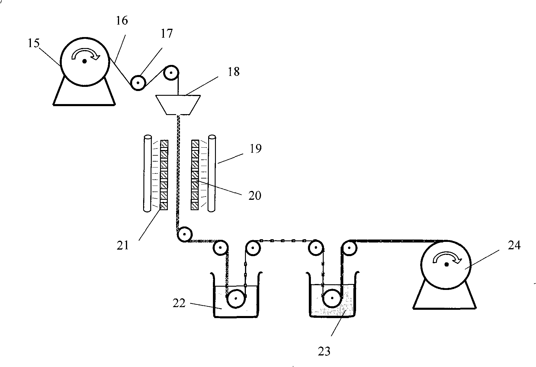
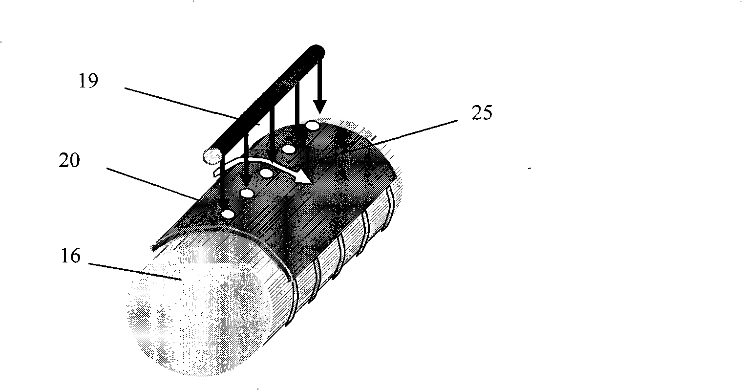
[0046] The parameter conditions used in each step of this embodiment are as follows: the conductive metal wire used is 300 μm stainless steel wire, the epoxy resin insulating glue is 623A-80UV glue, the ultraviolet light intensity is controlled to 2KW, the metal wire is kept still, and the ultraviolet light lamp is adjusted 19. The relative movement 25 of the mask plate 21 and the metal wire 16 is shown in Figure 2(c), the curing time is about 2 seconds, and the cathode of the micro-forming tool used for processing the spiral micro-groove is prepared, as shown in Figure 3 ( As shown in b), the thickness of the insulating layer is about 50 microns.

[0047] The electroforming metal is nickel, the electroplating solution is nickel sulfamate, the temperature of the electroplating solution is controlled at 30°C, the concentration of the electro...


PUM

PropertyMeasurementUnit
sizeaaaaaaaaaa

Abstract

The invention discloses an electrolytic machining technique of a micro-groove on an inner wall surface of a small aperture and a device. The technique is that: a cathode of a forming tool of a variable cross-section structure which is provided with insulation sections and conductive sections at intervals and is made of conductive metal wires of 200 to 1000 mum is positioned in an unthreaded hole of a workpiece which is processed in advance by utilizing the electrolytic machining device of the invention, the workpiece is taken as an anode, then electrolytic solution is radially flowed along an electrode wire, the electrolytic machining is carried out in the unthreaded hole, the pressure of the electrolytic solution is maintained at 1 to 5 MPa, and the micro-groove structure is obtained at the inner wall surface of the unthreaded hole by flushing the products after the processing. The diameter size of the cathode of the forming tool which is prepared by adopting the ultra-violet light masking solidification technology and the electroforming process can be as small as a few hundred microns, and a rib cooling hole structure with the hole diameter size of about 1mm can be obtained by combining the electrolytic machining technique. The adopted technical process of the invention is easy to master and has small investment, the minimal hole diameter which can be processed is small, and the processing precision is high.

Description

(1) Technical field [0001] The invention relates to an electrolytic machining process and device for fine grooves on the inner wall of a small aperture, and belongs to the technical field of electrolytic machining. (2) Background technology [0002] Energy issues are one of the major issues in the world today. my country's "Eleventh Five-Year Plan" energy policy requires energy consumption to be reduced by 20%, which shows the urgency and necessity of energy conservation. In addition, with the rapid development of industry and the emergence of large-scale and ultra-large-scale integrated circuits, while promoting the development of technology and information revolutions, higher requirements are placed on related technologies, such as the development of high-performance aeroengines , requires the development of effective cooling methods to reduce the heat load on the engine blades to ensure the normal operation of the engine; in recent years, the development of effective cool...

Claims


Application Information

Patent Timeline
Patent Type & Authority Applications(China)
IPC IPC(8): B23H3/00B23H3/04B23H3/06B23H3/08B23H3/10
Inventor 王明环彭伟章巧芳
Owner ZHEJIANG UNIV OF TECH
Why Eureka
Try Eureka