Motor unit, manufacturing method therefor and recording disk driving apparatus

a technology of recording disk and motor unit, which is applied in the direction of bearing unit rigid support, magnetic circuit shape/form/construction, instruments, etc., can solve the problems of not cured ultraviolet curing adhesive, poor productivity, and long time-consuming cure time of adhesive, etc., and achieve high adhesive strength and good productivity

Active Publication Date: 2006-08-08
NIPPON DENSAN CORP
View PDF14 Cites 69 Cited by
  • Summary
  • Abstract
  • Description
  • Claims
  • Application Information

AI Technical Summary

Benefits of technology

[0009]It is an object of the present invention to provide a motor unit good in productivity and capable of having a high adhesive strength, a manufacturing method therefor and a recording disk driving apparatus.

Problems solved by technology

In a case where the above adhesives are used, the following problems occur, however.
A thermosetting adhesive has a high adhesive strength, but it takes a long time to cure the adhesive.
Therefore, because it accommodated the motor unit and the jig together in the oven for curing the thermosetting adhesive, the productivity might be not excellent.
An ultraviolet curing adhesive is fast in curing speed, but there arises a case where the ultraviolet curing adhesive is not cured since ultraviolet does not reach a site such as a deep narrow gap.
An anaerobic adhesive is fast in curing speed, but curing is limited to a deep, narrow gap and what's worse, there arises a case where things around or near the adhesive is contaminated by outgassing from the adhesive in an uncured state.

Method used


Image

  • Motor unit, manufacturing method therefor and recording disk driving apparatus
  • Motor unit, manufacturing method therefor and recording disk driving apparatus
  • Motor unit, manufacturing method therefor and recording disk driving apparatus

Examples


first embodiment

Overall Construction of Spindle Motor

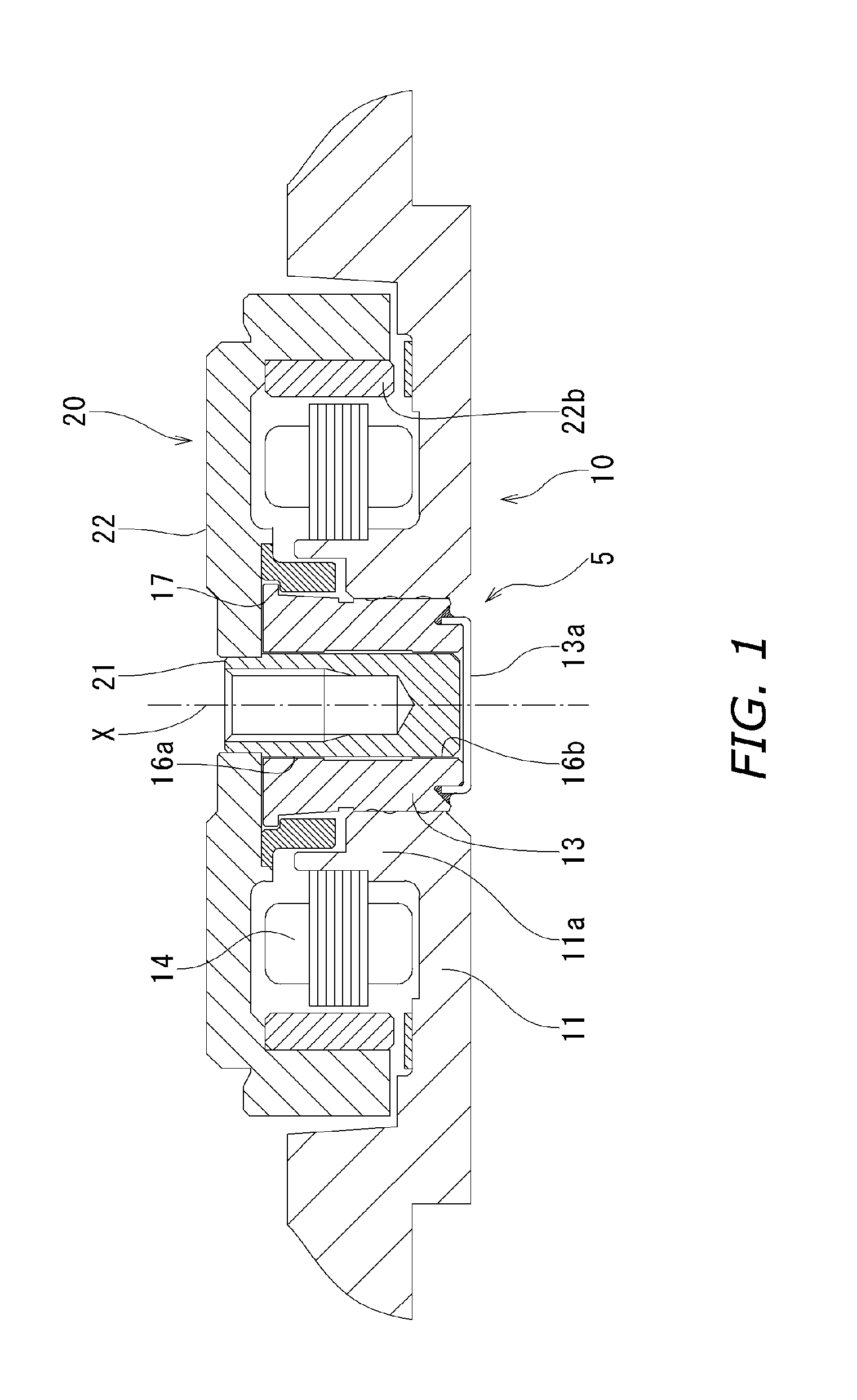
[0026]A spindle motor shown in FIG. 1 includes: a first housing member 11; a bearing assembly 5; and a rotor assembly 20. A hollow cylindrical section 11a is formed in the middle of the first housing member 11 approximately coaxially with the central axis X. The bearing assembly 5 is securely held by plural adhesives described later on an inner circumferential portion of the hollow cylindrical section 11a and a stator 14 is held on an outer circumferential portion of the hollow cylindrical section 11a.

[0027]The bearing assembly 5 includes: a sleeve 13 having a hollow cylindrical shape which made of a copper-based material such as phosphor bronze; a cover member 13a closing the lower end of the sleeve 13 in the axial direction thereof; and a shaft 21 facing an inner circumferential portion of the sleeve 13 with a micro gap interposed therebetween and rotating around the central axis X.

[0028]The rotor assembly 20 includes: the shaft 21; a rotor hu...

second embodiment

[0049]Description will be given of a second embodiment of the present invention with the reference to FIG. 6. Since a motor unit of the second embodiment is equivalent to that of the first embodiment in basic structure, corresponding parts are indicated with numbers in the hundreds so as to make clear correspondence between parts and description will be given only of different points.

[0050]An expanded clearance 111a2 open downward in the axial direction is, as shown in FIG. 6, formed in a lower portion in the axial direction of the hollow cylindrical section 111a of the first housing member 111. With the construction adopted, ultraviolet can be irradiated as deeply as the interior, thereby, enabling not only a highly rigid joint with higher precision to be realized, but also tilting of the shaft 121 to be prevented more.

[0051]The second embodiment as well has an action and effect similar to those of the first embodiment.

third embodiment

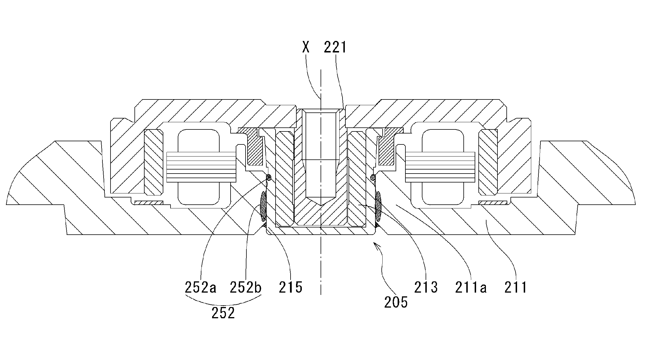
[0052]Description will be given of a third embodiment of the present invention with reference to FIG. 7. Since a motor unit of the third embodiment is equivalent to that of the first embodiment in basic construction, corresponding parts are indicated with numbers in the two hundreds to make clear correspondence between parts and description will be given only of different points.

[0053]A hollow cylindrical section 211a is provided in the middle of a first housing member 211 and a bearing assembly 205 is securely held on an inner circumferential portion of the hollow cylindrical section 211a with an adhesive section 252 interposed therebetween.

[0054]A bearing assembly 205 includes: a bearing holder 215 having a bottomed cylindrical shape; a sleeve 213 press fit in a space surrounded with an inner circumferential portion of the bearing holder 215 and securely held thereon by means such as adhesion; and a shaft 221 facing the inner circumferential portion of the sleeve 213 with a micro ...


PUM


Abstract

In a motor unit as an example of the invention, a bearing assembly 5 is securely held on an inner circumferential portion of a hollow cylindrical section 11a of a first housing member 11 with an adhesive section 52 interposed therebetween. The adhesive section 52 includes: a first adhering subsection 52a in which an anaerobic adhesive is present and a second adhering subsection 52b in which an externally stimulated curing type adhesive cured by heating or ultraviolet irradiation is present. Inserting the bearing assembly 5 into the hollow cylindrical section 11a produces a temporarily fixed state by the first adhering subsection 52a, thereby enabling the external stimulated curing type adhesive to be stably cured in the temporarily fixed state.

Description

BACKGROUND OF THE INVENTION[0001]1. Field of the Invention[0002]The invention relates to a motor unit having a bearing assembly forming a fluid dynamic pressure bearing supported on an inner circumferential portion of a housing member with an adhesive section interposed therein, a manufacturing method and a recording disk driving apparatus.[0003]2. Description of the Related Art[0004]Motor units each having a spindle motor unit equipped with a fluid dynamic pressure bearing in the presence of oil in a micro gap between a shaft and a hollow cylindrical sleeve have been employed in various kinds of electronic equipment such as a recording disk driving apparatus.[0005]In such a motor unit, a sleeve is securely held on an inner circumferential portion of a housing member with an adhesive section interposed therebetween. In the motor unit having such a holding structure, the sleeve is securely held on the housing member by an adhesive force of the adhesive section. Adhesives generally us...

Claims


Application Information

Patent Timeline
Patent Type & Authority Patents(United States)
IPC IPC(8): H02K7/08H02K15/00
CPCF16C35/02G11B19/2009H02K5/15H02K5/1675F16C41/008H02K15/14H02K7/085F16C2370/12H02K15/12F16C17/102F16C2226/40
Inventor GOMYO, MASATOSUGINOBU, SHINGO
Owner NIPPON DENSAN CORP
Why Eureka
Try Eureka