Microwave counter current continuous extraction apparatus

An extraction device and microwave countercurrent technology are applied in the structural field of microwave countercurrent extraction devices, which can solve the problems of increased cost, low concentration, no observation window, etc., and achieve the effects of reasonable design, reduced equipment cost, and simple structure.

Inactive Publication Date: 2007-03-28
TIANSHUI HUAYUAN PHARMA EQUIP TECH
View PDF1 Cites 21 Cited by
  • Summary
  • Abstract
  • Description
  • Claims
  • Application Information

AI Technical Summary

Problems solved by technology

In this technical solution, since the solid-liquid transmission device obliquely extends into the cavity from the opening of the front wall, and protrudes from the opening of the rear wall, the cavity of the microwave heater is relatively large, and the amount of extraction liquid filled is relatively large. The final concentration is relatively low, which increases the difficulty of the next process
At the same time, the cavity is much larger than the transmission device, and the solid material is distributed in all the spaces of the cavity, which will inevitably form a dead angle, so that the extracted slag cannot be discharged in time; the suppressors installed at the inlet and outlet of the outlet lengthen the entire equipment The length of the useless part increases the cost of the equipment; there is no observation window on the cavity of the heater, so it is impossible to observe the in and out conditions of the extract and the color of the extract

Method used


Image

  • Microwave counter current continuous extraction apparatus
  • Microwave counter current continuous extraction apparatus
  • Microwave counter current continuous extraction apparatus

Examples


Embodiment 1

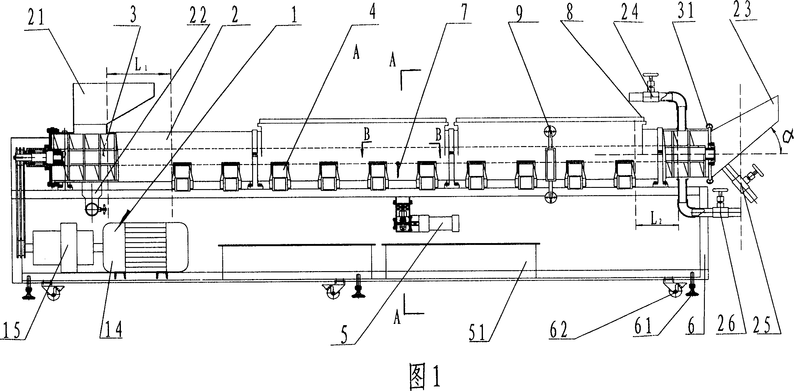
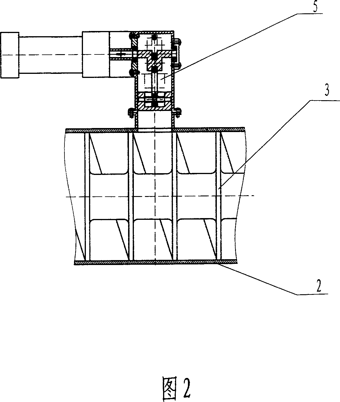
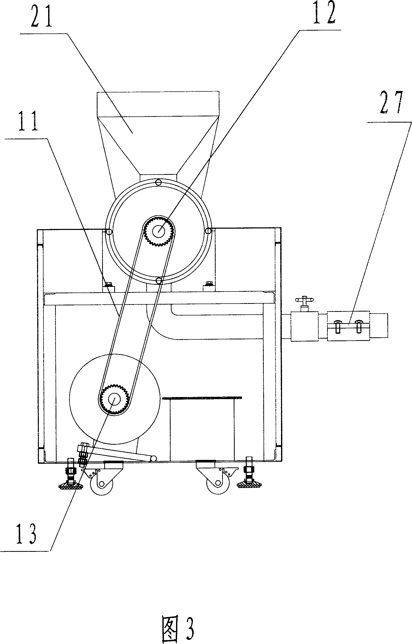
[0029] Embodiment 1: see Fig. 1, Fig. 2, Fig. 3, Fig. 9, microwave countercurrent continuous extraction device, extraction drum 2, its one end is provided with feeding hopper 21 and extraction solution outlet 22, and the other end is provided with slag outlet 23 and The extraction liquid inlet 24; the microwave system 4 is provided on the extraction drum 2, and the inner cavity of the extraction drum 2 is provided with a screw propeller 3. The main sprocket 13 is driven by the motor 14 through the speed reducer 15, and the main sprocket 13 drives the screw propeller 3 through the chain 11 and the sprocket 12. The microwave system 4 is located in the middle of the extraction drum 2 . The extraction drum 2 is arranged horizontally and is horizontal; the screw propeller 3 and the extraction drum 2 are both arranged horizontally and is horizontal, and the two axes coincide. The extraction drum 2 is provided with a pressurizing device 5 , and its pressure output port communicates ...

Embodiment 2

[0034]Embodiment 2: see Fig. 4, the screw propeller 3 that is provided with in the inner cavity of the extraction drum 2, the material used for the screw propeller 3 is polypropylene. Axial through-holes 31 are provided on its spiral blade surface. The diameter of the through hole 31 is φ1.5mm. The distance L between the axis of the feed hopper 21 and the start end of the microwave system 4 1 is 2500mm; the distance L between the end of the microwave system 4 and the end of the extraction drum 2 2 It is 2500mm. The diameter of screw propeller 3 is φ 3500mm. The rest of the structure is the same as the previous example.

Embodiment 3

[0035] Embodiment 3: See FIG. 1 , on the basis of the above two embodiments, the material used for the screw propeller 3 is ceramics. The rest of the structure is the same as Example 1.


PUM


Abstract

The present invention mainly is relates to an extraction equipment used in the fields of food industry, pharmaceuticals industry and chemical industry. In particular, it relates to a microwave countercurrent continuous extraction equipment. It includes the following several portions: extraction drum, its oned end is equipped with feed funnel and extract outled, its another end is equipped with residuum outlet and extract inlet; on the extraction drum a microwave system is set, in the inner cavity of extraction drum a screw-type propeller is mounted, said screw-type propeller is driven by drive device. Besides, said invention also provides its working principle and concrete operation method.

Description

Technical field: [0001] The invention mainly relates to an extraction equipment used in industries such as food, pharmacy, and chemical industry, and particularly relates to the structure of a microwave countercurrent extraction device. Background technique: [0002] Various extraction devices are widely used in food, pharmaceutical, chemical and other industries. The traditional method is to add the extraction liquid to the extraction device, and conduct heat from the outside to the inside by heat conduction, heat radiation, etc., so as to realize the heating, concentration, and extraction of materials. Extraction, sterilization, etc. With the expansion of the application field of microwave technology, microwave extraction appears and develops rapidly. The basic principle is that the microwave penetrates the extracted material and reaches the internal microtube bundle and glandular cell system of the material. Due to the absorption of microwave energy, the internal tempera...

Claims


Application Information

Patent Timeline
Patent Type & Authority Applications(China)
IPC IPC(8): B01D11/02B01J19/12
Inventor 李晟
Owner TIANSHUI HUAYUAN PHARMA EQUIP TECH
Why Eureka
Try Eureka