
Spinneret plate

A spinneret and spinneret hole technology, which is applied in the field of fiber production, can solve the problems of failing to meet technological requirements, spinning difficulties, and too many tows, and achieve the effect of good spinning effect.

Inactive Publication Date: 2013-01-02
ZHANGJIAGANG HENGMEI TEXTILE
View PDF5 Cites 2 Cited by
  • Summary
  • Abstract
  • Description
  • Claims
  • Application Information

AI Technical Summary

Problems solved by technology

During the spinning production process, the high-temperature melt is extruded from the spinneret body under a certain pressure, and forms dense high-temperature melt streams through the spinneret holes. The temperature of these melt streams is very high, generally between 290 and 325 °C. During the process, through the ring blowing cooling device, it needs to be uniformly cooled in a certain spinning process and in a short time to form a stable pre-drawn filament with a certain degree of crystallinity and pre-orientation; due to the large diameter of the spinneret, There are many tows, and it is difficult for the cooling air to pass through the dense layers of peripheral tows to reach the middle of the spinneret. The tows located in the middle of the spinneret will be difficult to spin because the cooling cannot meet the process requirements, which will affect product quality.

Method used


Image

  • Spinneret plate

Examples


Embodiment Construction

[0008] A spinneret of the present invention will be further described in detail below through specific embodiments.

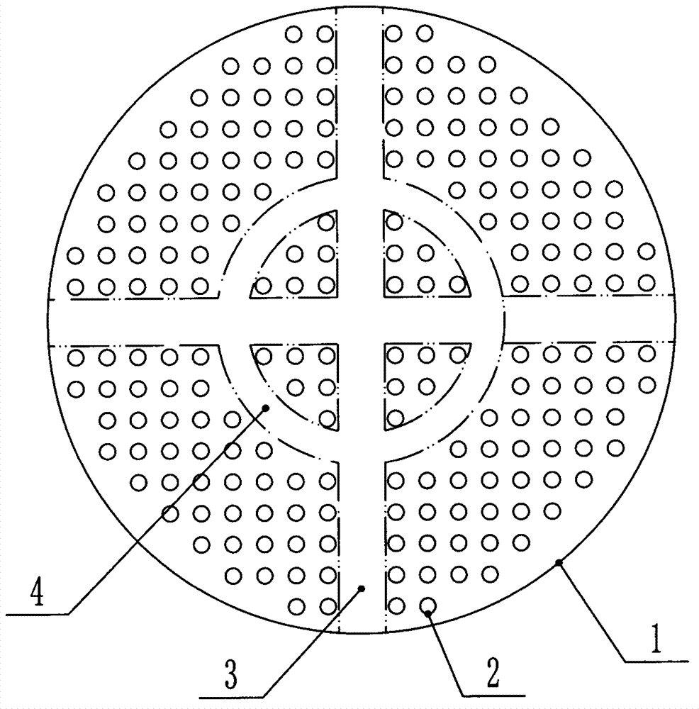
[0009] like figure 1 As shown, a spinneret includes: a spinneret body 1, a spinneret body 1 is provided with a spinneret hole 2, and the spinneret body 1 is provided with a spinneret leading from the periphery of the spinneret to the spinneret The cross-shaped ventilation channel 3 in the middle of the plate and the annular ventilation channel 4 with the center of the spinneret as the center of the circle.

[0010] The above-mentioned spinneret, by setting the cross-shaped air passage 3 and the annular air passage 4 on the spinneret body 1, because there is no spinneret hole 2 in the cross-shaped air passage 3 and the annular air passage 4 area and communicate with each other, it is also There is no tow to block the passage of the cooling air, and the cooling air can enter the middle of the spinneret from the periphery of the spinneret through the air duct, so...


PUM


Abstract

The invention relates to a spinneret plate which comprises a spinneret plate body, wherein spinneret holes, a cross air ventilation duct leading to the center of the spinneret plate from the periphery of the spinneret plate and an annular ventilation duct with the center of the spinneret plate serving as the circle center are arranged on the spinneret plate body. The spinneret plate is suitable for spinning, and all the tows sprayed out by the spinneret plate can be cooled to meet the process requirements.

Description

technical field [0001] The invention relates to the technical field of fiber production, in particular to a spinneret. Background technique [0002] The structure of the spinneret for spinning commonly used at this stage includes: a spinneret body, and the spinneret holes are evenly and densely distributed on the body. In the spinning production process, the high-temperature melt is extruded from the spinneret body under a certain pressure, and a dense stream of high-temperature melt is formed through the spinneret hole. During the process, after passing through the ring blowing cooling device, it needs to be uniformly cooled within a certain spinning distance and in a very short time to form a stable pre-drawn yarn with a certain degree of crystallinity and pre-orientation; due to the large diameter of the spinneret, There are many tows, and it is difficult for the cooling air to pass through the densely covered peripheral tows to the middle of the spinneret. The tows loca...

Claims


Application Information

Patent Timeline
IPC IPC(8): D01D4/02
Inventor 盛忠勤
Owner ZHANGJIAGANG HENGMEI TEXTILE
Learn More