Spinneret plate

A spinneret and spinneret hole technology, applied in spinneret assemblies, textiles and papermaking, etc., can solve the problems of not meeting the technological requirements, difficulty in spinning, too many tows, etc., and achieve better spinning effect. Effect

Inactive Publication Date: 2013-09-11
ZHANGJIAGANG ZANXIN SPECIAL FIBER
View PDF9 Cites 4 Cited by
  • Summary
  • Abstract
  • Description
  • Claims
  • Application Information

AI Technical Summary

Problems solved by technology

During the spinning production process, the high-temperature melt is extruded from the spinneret body under a certain pressure, and forms dense high-temperature melt streams through the spinneret holes. The temperature of these melt streams is very high, generally between 290 and 325 °C. During the process, through the ring blowing cooling device, it needs to be uniformly cooled in a certain spinning process and in a short time to form a stable pre-drawn filament with a certain degree of crystallinity and pre-orientation; due to the large diameter of the spinneret, There are many tows, and it is difficult for the cooling air to pass through the dense layers of peripheral tows to reach the middle of the spinneret. The tows located in the middle of the spinneret will be difficult to spin because the cooling cannot meet the process requirements, which will affect product quality.

Method used


Image

  • Spinneret plate

Examples


Embodiment Construction

[0009] A spinneret according to the present invention will be further described in detail through specific examples below.

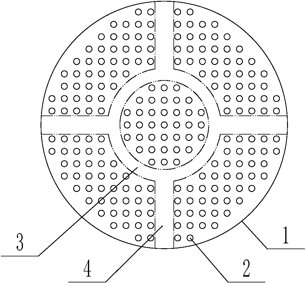
[0010] like figure 1 As shown, a spinneret includes: a spinneret body 1, a spinneret hole 2 is arranged on the spinneret body 1, and an annular ring with the center of the spinneret as the center is arranged on the spinneret body 1. The air passage 3, the spinneret body 1 is also provided with four straight air passages 4, the four straight air passages 4 are evenly distributed along the circumferential direction of the spinneret body 1, and one end of each straight air passage 4 is connected with the annular air passage 3 The other end of the straight air passage 4 communicates with the outside of the spinneret body 1 .

[0011] The above-mentioned spinneret, by setting the straight air passage 4 and the annular air passage 3 on the spinneret body 1, since there are no spinneret holes in the area of ​​the straight air passage 4 and the annular air pass...


PUM


Abstract

The invention relates to a spinneret plate which comprises a spinneret plate body. Spinneret holes are formed in the spinneret plate body, an annular ventilation duct taking the center of the spinneret plate as the center of a circle is arranged on the spinneret plate body, at least one linear ventilation duct is further arranged on the spinneret plate body, and one ends of the linear ventilation ducts are communicated with the annular ventilation ducts while the other ends of the same are communicated with the outside of the spinneret plate body. By the spinneret plate, high-temperature melt sprayed by the spinneret plate can be within a set time period and on a certain spinning line and can be all uniformly cooled to meet process requirements and form stable pre-stretching threads with certain crystallinity and pre-orienting degree, so that spinning effect is better.

Description

technical field [0001] The invention relates to the technical field of fiber production equipment, in particular to a spinneret. Background technique [0002] The structure of the spinneret commonly used for spinning at the present stage includes: the spinneret body, and the spinneret holes are evenly and densely distributed on the body. During the spinning production process, the high-temperature melt is extruded from the spinneret body under a certain pressure, and forms dense high-temperature melt streams through the spinneret holes. The temperature of these melt streams is very high, generally between 290 and 325 °C. During the process, after going through the cooling device of the ring blower, it needs to be uniformly cooled in a certain spinning process and in a short time to form a stable pre-drawn filament with a certain degree of crystallinity and pre-orientation; due to the large diameter of the spinneret, There are many tows, and it is difficult for the cooling a...

Claims


Application Information

Patent Timeline
Patent Type & Authority Applications(China)
IPC IPC(8): D01D4/02
Inventor 陈志伟王海娟方乐施丹阳顾振峰
Owner ZHANGJIAGANG ZANXIN SPECIAL FIBER
Why Eureka
Try Eureka