Structure bending corner locking mechanism for rotating guide drilling tool

A technology of rotary steerable drilling and locking mechanism, applied in directional drilling and other directions, can solve the problems of increasing design difficulty, narrow space for small-diameter drilling tools, affecting work efficiency and reliability, etc., achieving simple structure, good practicability, Good applicability

Inactive Publication Date: 2013-01-09
CHINA UNIV OF PETROLEUM (EAST CHINA)
View PDF6 Cites 6 Cited by
  • Summary
  • Abstract
  • Description
  • Claims
  • Application Information

AI Technical Summary

Problems solved by technology

In view of the narrow internal space of dynamic pointing rotary steerable drilling tools, especially small-diameter drilling tools, the volume and installation position of the motor will inevitably be limited, which may affect its working efficiency and reliability
In addition, the introduction of power supply lines and the demand for power supply voltage stabilization have also increased the difficulty of design to a certain extent.

Method used


Image

  • Structure bending corner locking mechanism for rotating guide drilling tool
  • Structure bending corner locking mechanism for rotating guide drilling tool
  • Structure bending corner locking mechanism for rotating guide drilling tool

Examples


Embodiment 1

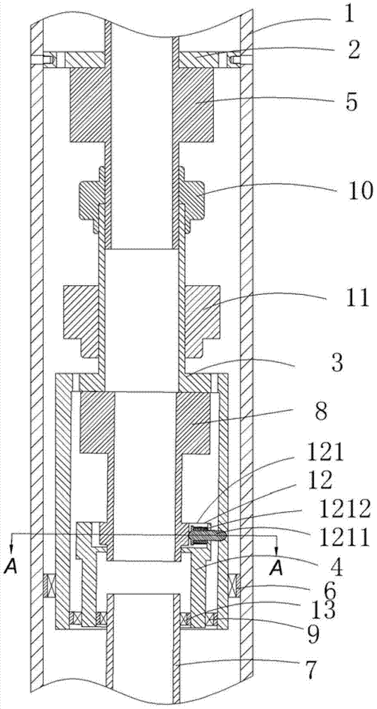
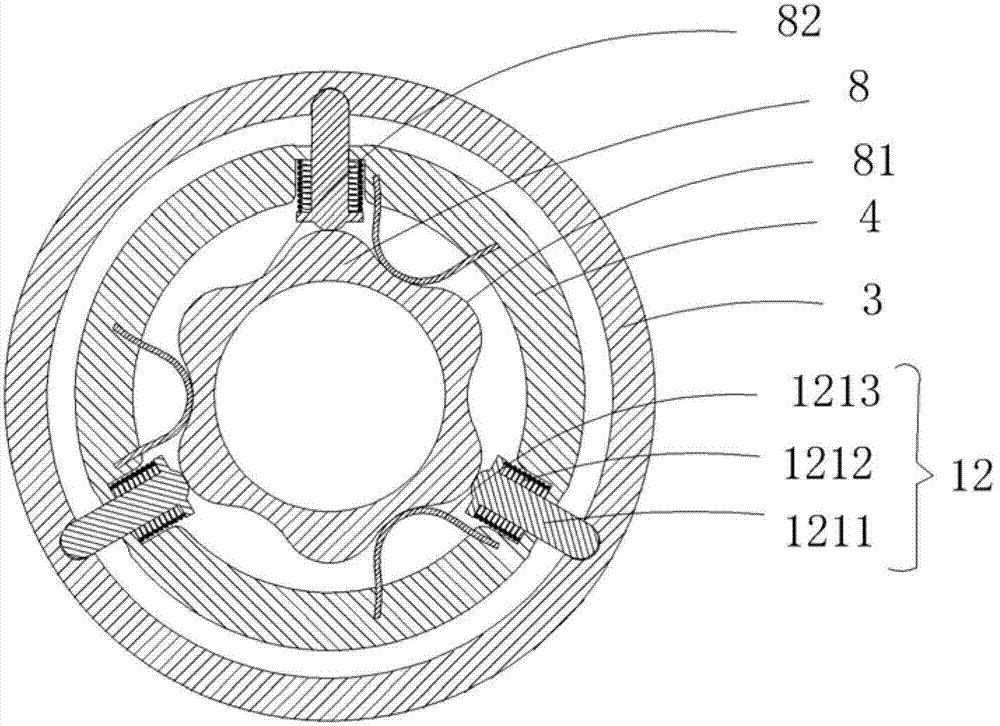
[0032] Figure 1 to Figure 3 shows a first embodiment of the invention,

[0033] as attached Figure 1-3As shown, a structural angle locking mechanism for a rotary steerable drilling tool includes a rotating outer cylinder 1, a support plate 2, a stabilizing platform 3, an eccentric ring 4, a stabilizing platform servo motor 5, a stabilizing platform connecting bearing 6, a drill Shaft 7, eccentric ring servo motor 8, eccentric ring connecting bearing 9, coupling 10 and conductive slip ring 11, drill shaft 7 is set at the bottom of rotating outer cylinder 1, support plate 2 is set inside rotating outer cylinder 1, and stabilizes the platform The servo motor 5 is arranged on the lower end surface of the support plate 2, the upper end of the stabilizing platform 3 is connected with the stabilizing platform servo motor 5, the lower end of the stabilizing platform 3 is sealed and matched with the inner wall of the rotating outer cylinder 1 through the stabilizing platform connect...

Embodiment 2

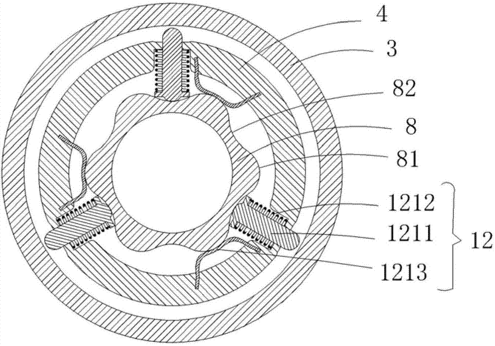
[0040] Figure 4 to Figure 8 A second embodiment of the invention is shown,

[0041] See Figure 4 to Figure 8 , this embodiment is basically the same as Embodiment 1, except that the structural locking mechanism 12 is an electromagnetic locking mechanism 122 .

[0042] The electromagnetic locking mechanism 122 includes an electromagnetic ring 1221, an electromagnetic spring 1222, a locking ring 1223 and a locking ring sleeve. The electromagnetic ring 1221, the electromagnetic spring 1222 and the locking ring are sleeved on the upper extension shaft of the eccentric ring, and the electromagnetic spring 1222 is disposed between the electromagnetic ring 1221 and the locking ring 1223 .

[0043] The inside of the stable platform 3 is provided with a stable platform internal groove 31, the outside of the eccentric ring 4 is provided with an eccentric ring bump 41, and the inside of the locking ring 1223 is provided with a locking ring groove 12231 that matches the eccentric ring...


PUM


Abstract

The invention discloses a structure bending corner locking mechanism for rotating a guide drilling tool. The structure bending corner locking mechanism comprises an outer rotation barrel, a mounting plate, a stable platform, an eccentric ring, a stabilized platform servo motor, a stabilized platform connection bearing, a drilling shaft, an eccentric ring servo motor, an eccentric ring connection bearing, a coupler and an electric conduction sliding ring, and the structure bending corner locking mechanism is arranged between the stable platform and the eccentric ring. A setting structure bending corner is transmitted to the drilling shaft through a drilling shaft connection bearing arranged inside the eccentric ring, then is transmitted to a drill and further achieves changes of structure bending corners in a drilling process. The structure bending corner locking mechanism is simple in structure, coordination can effectively reduce interference of external vibration and impact on drilling tools, work stability is improved, the structure bending corner locking mechanism is arranged, locking and unlocking functions of the structure bending corner can be achieved, use is convenient, deflecting capability and angle dropping capability are improved, and applicability is good.

Description

technical field [0001] The invention relates to the technical field of dynamic pointing rotary steerable drilling tools, in particular to a structural angle locking mechanism for rotary steerable drilling tools. Background technique [0002] The dynamic pointing rotary steerable drilling tool system is the highest stage in the development of drilling technology in the world today, and represents the development direction of high-precision directional drilling technology. The system is a closed-loop automatic control system integrating machinery, electricity and hydraulics. The complete rotation of the parts is the main technical feature. [0003] The deflection capability of the dynamic pointing rotary steerable drilling tool system does not depend on the contact with the well wall. By keeping the stable platform in a static state and adjusting the relative position of the offset steering mechanism and the stable platform, the azimuth and well Bevel control. Due to the com...

Claims


Application Information

Patent Timeline
Patent Type & Authority Applications(China)
IPC IPC(8): E21B7/06
Inventor 鄢志丹耿艳峰杨锦舟吴仲华
Owner CHINA UNIV OF PETROLEUM (EAST CHINA)
Why Eureka
Try Eureka