Water stop and diversion tank of water chiller and application method

A chiller and shunt tank technology, which is applied in the direction of refrigerators, refrigeration components, mechanical equipment, etc., can solve the problems of difficult connection of the ports of the separation structure, troublesome operation of water stop and diversion, lack of shunt structure, etc., and achieve the effect of convenient connection

Active Publication Date: 2021-01-22
深圳市东星制冷机电有限公司
View PDF6 Cites 0 Cited by
  • Summary
  • Abstract
  • Description
  • Claims
  • Application Information

AI Technical Summary

Problems solved by technology

The principle of the chiller is to inject a certain amount of water into the internal water tank of the machine, cool the water through the chiller refrigeration system, and then the water pump inside the machine injects low-temperature frozen water into the equipment that needs to be cooled, and the chilled water transfers the heat inside the machine Take it away, and return the high-temperature hot water to the water tank again to cool down. In this way, the cooling is circulated and exchanged to achieve the effect of cooling the equipment. Today's industrial chillers lack a shunt structure inside, and the ports of the separated structure are difficult to connect with external connection equipment. Trouble with water diversion

Method used


Image

  • Water stop and diversion tank of water chiller and application method
  • Water stop and diversion tank of water chiller and application method
  • Water stop and diversion tank of water chiller and application method

Examples


Embodiment Construction

[0033] The following will clearly and completely describe the technical solutions in the embodiments of the present invention with reference to the accompanying drawings in the embodiments of the present invention. Obviously, the described embodiments are only some, not all, embodiments of the present invention. Based on the embodiments of the present invention, all other embodiments obtained by persons of ordinary skill in the art without making creative efforts belong to the protection scope of the present invention.

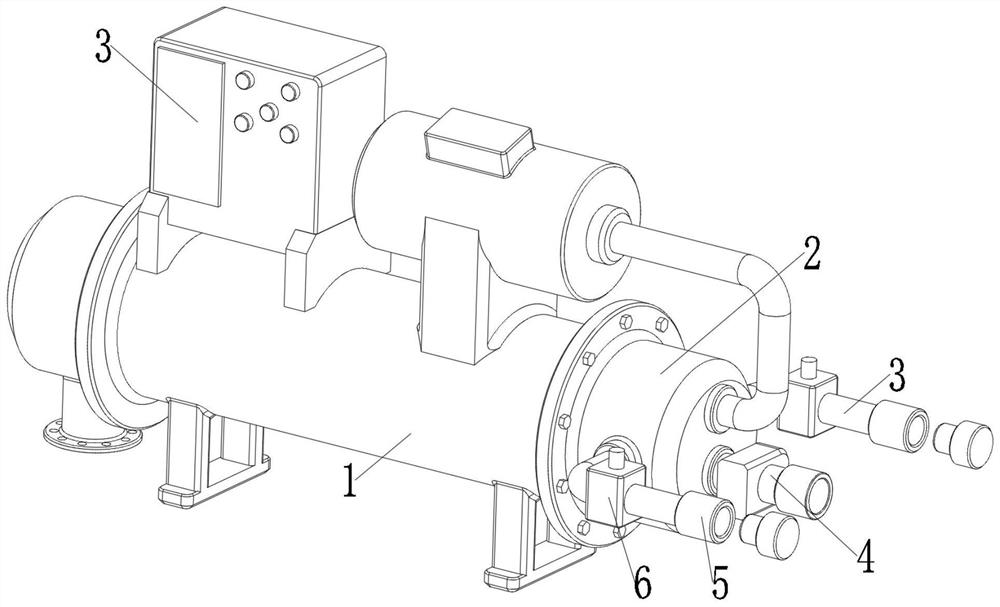
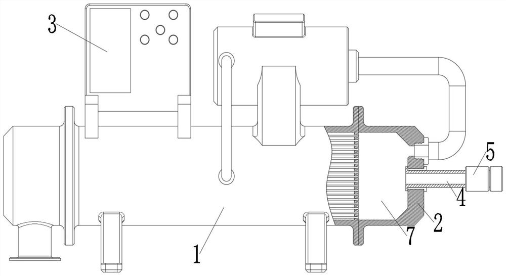
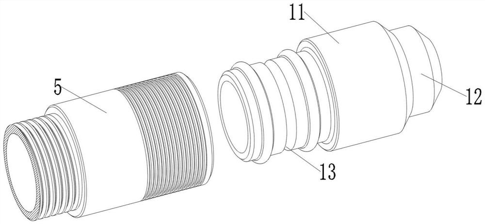
[0034] Such as Figure 1-5 As shown, the present invention provides a technical solution: a water-stop water-stop shunt tank for a chiller, including a tank body 1, a shunt end 2, a side pipe 3, a main flow pipe 4, a sliding sleeve 5, a water-stop structure 6, a cavity 7, and a port 8. Limiting groove 9, locking bead 10, external connecting pipe 11, sealing ring 12, locking groove 13, plug 14, power box 15, micro motor 16, connecting shaft 17, torque gear 18, ...


PUM


Abstract

The invention discloses a water stop and diversion tank of a water chiller. The tank comprises a tank body, wherein a diversion end is fixedly installed at one end of the tank body, side pipes are fixedly installed on the upper surface of the tank body and are symmetrically installed at the two sides of the diversion end, a main flow pipe is fixedly installed on the outer surface of one end of thediversion end, a sliding sleeve is arranged at one end of each side pipe, and a sliding sleeve is arranged at one end of the main flow pipe; a water stop structure is fixedly installed at the outer side of each side pipe, a water stop structure is fixedly installed at the outer side of the main flow pipe, a cavity is formed in the diversion end, an end opening is movably connected into each sliding sleeve, a limiting groove is formed in the inner wall of each sliding sleeve, a locking ball is movably connected to the inner wall of one end of each end opening, an external connecting pipe is fixedly installed in each end opening, and a locking groove is formed in one end of each external connecting pipe; and sealing rings are fixedly installed at the two sides of each locking groove, and aplug is fixedly installed at the other end of each external connecting pipe. According to the water stop and diversion tank of the water chiller, the functions of diversion and water stop are achieved, and operation is more convenient when the tank is connected with external connecting equipment.

Description

technical field [0001] The invention relates to the technical field of industrial water chillers, in particular to a water stop distribution tank of a water chiller, more specifically to a water stop distribution tank of a water chiller and a use method thereof. Background technique [0002] Chiller is a kind of water cooling equipment, which can provide constant temperature, constant flow and constant pressure cooling equipment. The principle of the chiller is to inject a certain amount of water into the internal water tank of the machine, cool the water through the chiller refrigeration system, and then the water pump inside the machine injects low-temperature frozen water into the equipment that needs to be cooled, and the chilled water transfers the heat inside the machine Take it away, and return the high-temperature hot water to the water tank again to cool down. In this way, the cooling is circulated and exchanged to achieve the effect of cooling the equipment. Today'...

Claims


Application Information

Patent Timeline
Patent Type & Authority Applications(China)
IPC IPC(8): F25B41/00F25B41/20F16L37/23F16L37/47F16K31/04F16K31/53
CPCF25B41/00
Inventor 不公告发明人
Owner 深圳市东星制冷机电有限公司
Why Eureka
Try Eureka