
Driving circuit of organic light-emitting element and operating method thereof

A technology of organic light-emitting elements and driving circuits, which can be applied to instruments, static indicators, etc., can solve problems such as brightness decline of organic light-emitting diodes, and achieve the effects of compensating for non-uniformity, compensating voltage attenuation, and compensating aging problems.

Inactive Publication Date: 2016-05-04
CPTF VISUAL DISPLAY (FUZHOU) LTD +1
View PDF3 Cites 0 Cited by
  • Summary
  • Abstract
  • Description
  • Claims
  • Application Information

AI Technical Summary

Problems solved by technology

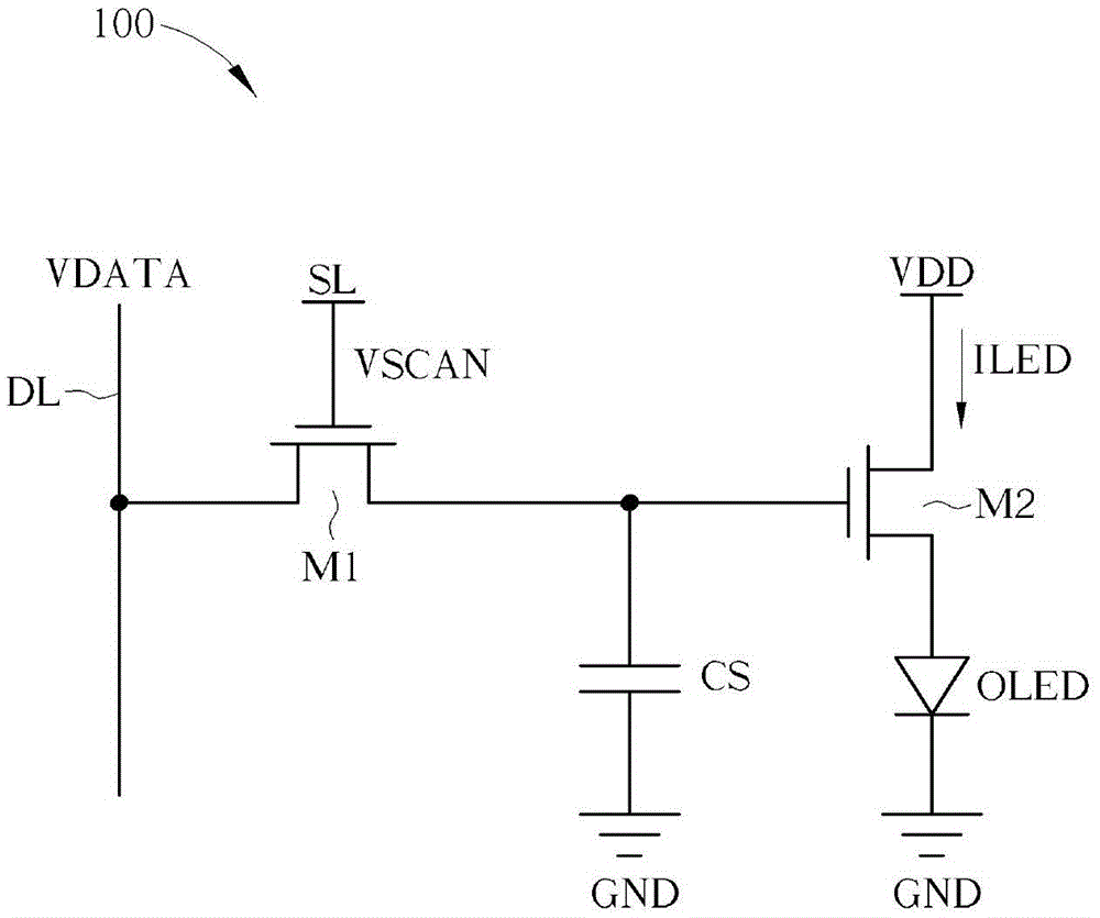
[0011] Because the organic light-emitting diode is given an operating bias for a long time, the voltage across the organic light-emitting diode will gradually rise, resulting in a serious decline in the brightness of the organic light-emitting diode.
[0012] Therefore, the driving circuit 100 is not a good driving circuit for organic light emitting diodes

Method used


Image

  • Driving circuit of organic light-emitting element and operating method thereof
  • Driving circuit of organic light-emitting element and operating method thereof
  • Driving circuit of organic light-emitting element and operating method thereof

Examples


Embodiment Construction

[0062] Please refer to Figure 4 or Figure 5 , Figure 4 A schematic diagram illustrating a driving circuit 400 for an organic light-emitting element according to an embodiment of the present invention, and Figure 5 It is a schematic diagram illustrating the operation sequence of the driving circuit 400, wherein the driving circuit 400 is a current programming driving circuit. Such as Figure 4 As shown, the drive circuit 400 includes a switch module 402 , a capacitor 404 and a drive unit 406 , and the switch module 402 includes a first switch unit 4022 and a second switch unit 4024 . The first switch unit 4022 is used to connect to a data line DL. The second switch unit 4024 is used to connect to an organic light emitting element 408, wherein the organic light emitting element 408 can be an organic light emitting diode. Such as Figure 5 As shown, during an encoding period (period T1), the first switch unit 4022 is turned on and the second switch unit 4024 is turned o...


PUM


Abstract

The invention discloses a driving circuit of an organic light-emitting element. The driving circuit comprises a switching module, a capacitor and a driving unit, wherein the switching module comprises a first switching unit and a second switching unit. The first switching unit is connected with a data wire; the second switching unit is connected with the organic light-emitting element; during an encoding period, the first switching unit is turned on and the second switching unit is turned off; and during a light-emitting period, the first switching unit is switched off and the second switching unit is turned on. The capacitor is connected with the first switching unit and is used for charging to data voltage according online data current of the data during the encoding period. The driving unit is connected with the capacitor and the second switching unit and is used for generating a driving current according to the data voltage during the light-emitting period, so as to drive the organic light-emitting element.

Description

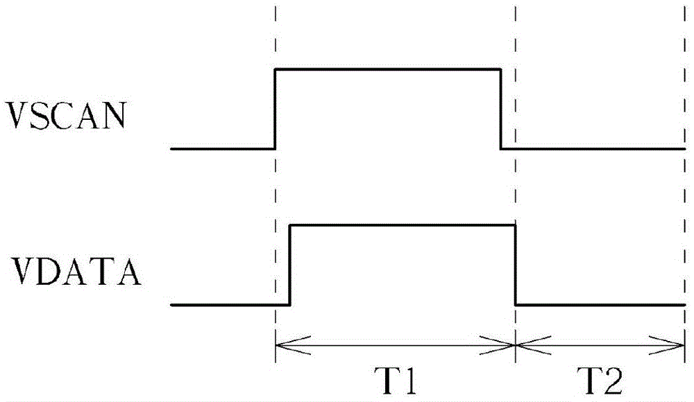
technical field [0001] The present invention relates to a driving circuit of an organic light-emitting element and its operating method, in particular to a method of using current coding to make the driving current generated by the driving circuit equal to the data current when the organic light-emitting element is driven by a capacitor, and is compatible with any manufacturing process of a thin film transistor. A driving circuit of a parameter-independent organic light-emitting element and an operating method thereof. Background technique [0002] Please refer to figure 1 and figure 2 , figure 1 It is a schematic diagram illustrating a driving circuit 100 using voltage programming (voltage programming) organic light-emitting diodes for the prior art, and figure 2 It is a schematic diagram illustrating the operation sequence of the driving circuit 100 . Such as figure 1 and figure 2 As shown, in the period T1, the scan signal VSCAN on a scan line SL is turned on, so...

Claims


Application Information

Patent Timeline
Patent Type & Authority Patents(China)
IPC IPC(8): G09G3/3233
Inventor 孙伯彰黄金海陈冠妤黄思齐
Owner CPTF VISUAL DISPLAY (FUZHOU) LTD
Learn More