
Plasma chamber system and method for cineration of photolithographic patterns thereby

A photoresist pattern and plasma chamber technology, which is applied to the plasma chamber system and the field of ashing photoresist patterns using the system, can solve the problems of inability to control plasma uniformity and the like

Inactive Publication Date: 2006-05-31
PSK INC
View PDF0 Cites 9 Cited by
  • Summary
  • Abstract
  • Description
  • Claims
  • Application Information

AI Technical Summary

Problems solved by technology

[0013] However, the commonly used capacitively coupled plasma chamber system can effectively increase the etching rate by increasing the concentration of the plasma formed in the chamber, but it cannot control the uniformity of the plasma in the spatial position

Method used


Image

  • Plasma chamber system and method for cineration of photolithographic patterns thereby
  • Plasma chamber system and method for cineration of photolithographic patterns thereby
  • Plasma chamber system and method for cineration of photolithographic patterns thereby

Examples


Embodiment Construction

[0034]Preferred embodiments of the present invention will be described in detail below with reference to the accompanying drawings. However, the present invention can be implemented in various ways without being limited to the embodiments described here. Rather, these embodiments are provided so that this disclosure will be thorough, and will fully convey the scope of the invention to those skilled in the art. In the drawings, layer thicknesses and regions where layers are located are exaggerated for clarity. It will also be understood that when a layer is referred to as being on another layer or substrate, it can be directly on the other layer or substrate, or intervening layers may also be present therebetween.

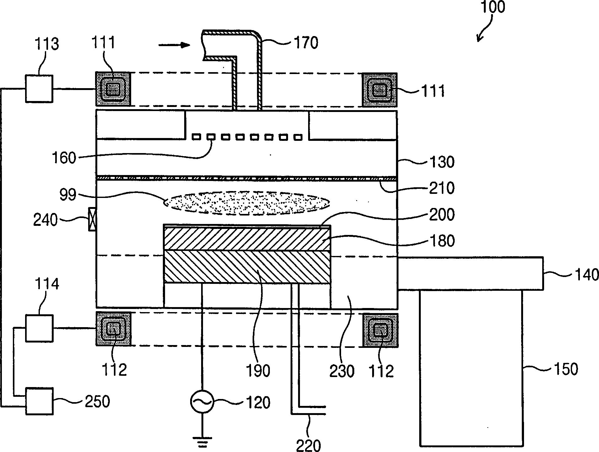
[0035] figure 2 The plasma chamber system of the present invention is schematically shown.

[0036] refer to figure 2 , the plasma chamber system 100 according to the present invention includes: a process chamber 130 , a supply pipe 170 for supplying a process...


PUM


Abstract

Disclosed is a plasma chamber system and method of ashing a photoresist pattern formed on a substrate having a low-k dielectric layer using the same. The plasma chamber system includes a process chamber, a wafer chuck arranged in the process chamber, a bottom radio-frequency power source electrically connected to the wafer chuck, a top electrode arranged on the wafer chuck, top Helmholtz coils arranged on the process chamber, and bottom Helmholtz coils arranged under the process chamber.

Description

[0001] related application [0002] This application claims priority from Korean Patent Application No. 2004-97461 filed on Nov. 25, 2004, the entire contents of which are hereby incorporated by reference. technical field [0003] The present invention relates to a semiconductor manufacturing device and a method of manufacturing a semiconductor device using the device, in particular, to a plasma chamber system and a method for ashing a photoresist pattern formed on a substrate having a low-k dielectric layer using the system . Background technique [0004] In order to meet the needs of miniaturization and high integration of highly integrated semiconductor elements and to accelerate the driving speed of highly integrated semiconductor elements, research on the formation of interlayer (or intermetallic) insulating layers using low-K dielectric materials has been widely carried out . Since SiO is widely used as an interlayer insulating layer 2 The dielectric constant of SiO...

Claims


Application Information

Patent Timeline
IPC IPC(8): G03F7/36
CPCG03F7/427
Inventor 李畅源
Owner PSK INC
Learn More