

Mobile communication device
A technology of mobile communication equipment and conductive bumps, which is applied in the direction of telephone structure, connecting contact material, etc., to achieve the effect of grounding
- Summary
- Abstract
- Description
- Claims
- Application Information
AI Technical Summary
Problems solved by technology
Method used
Image

Examples
Embodiment Construction
[0023] The present invention will be described in detail below in conjunction with the accompanying drawings and embodiments.
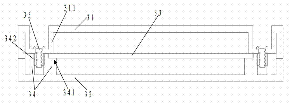
[0024] refer to image 3 , image 3 It is a structural schematic diagram of the mobile communication device according to the first embodiment of the present invention. Such as image 3 As shown, in this embodiment, the mobile communication device includes: a conductive casing 31 , a plastic casing 32 and a circuit board 33 .
[0025] Wherein, the conductive shell 31 includes a conductive protrusion 311 . In this embodiment, the conductive protrusion 311 is preferably integrally formed with the conductive housing 31. In other embodiments, the conductive protrusion 311 may also be welded on the conductive housing 31 or fixed on the conductive housing 31 by other means. superior.
[0026] It should be noted that, in this embodiment, the conductive shell 31 is preferably a metal shell, and in other embodiments, the conductive shell 31 can also be a p...
PUM
 Abstract
Description
Claims
Application Information