Open-loop Hall current sensor

A Hall current and sensor technology, applied in the field of sensors, can solve the problems of easy breakage, many current sensors, and cumbersome assembly process, and achieve the effects of improving stability, increasing contact area, and improving reliability.

Inactive Publication Date: 2021-12-14
NINGBO CRRC TIMES TRANSDUCER TECH CO LTD
View PDF6 Cites 1 Cited by
  • Summary
  • Abstract
  • Description
  • Claims
  • Application Information

AI Technical Summary

Problems solved by technology

First, due to the large number of components of the current sensor, the assembly process is relatively cumbersome;
Second, when the double-conducting copper foil tape 500 is nested and connected with the iron core 200, the corresponding length of the double-conducting copper foil tape 500 is manually cut, and the insulating layer on the surface of the iron core 200 needs to be ground to realize the electrical connection between the two. However, due to the thin texture of the double-lead copper foil tape 500, it is easy to break, and the double-lead copper foil tape 500 and the iron core 200 are fixed by colloid, and the colloid has tension. When the current sensor is working in a high and low temperature environment , the colloid will crack the double conductive copper foil tape 500, thus affecting the performance of the sensor to detect current
[0003] Third, one side of the sheath 600 is nested and connected to the air gap 210 on the iron core 200, and fixed by colloid, and the other end of the sheath 600 is welded to the main circuit printed board 400, wherein the main circuit printed board 400 is screwed Installed on the housing 100, therefore, no specific structure is provided in this connection method to realize the fixation of the iron core 200 in the housing 100. When the current sensor works in a high and low temperature environment, the instability of the installation of the iron core 200 may affect the detection of the sensor. current performance

Method used


Image

  • Open-loop Hall current sensor
  • Open-loop Hall current sensor
  • Open-loop Hall current sensor

Examples


Embodiment 2

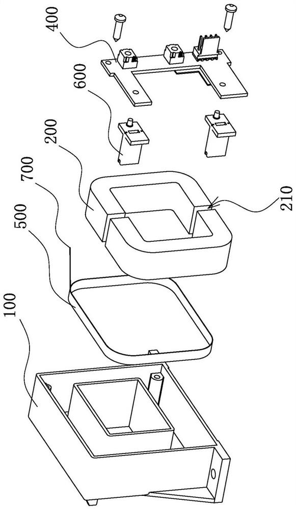
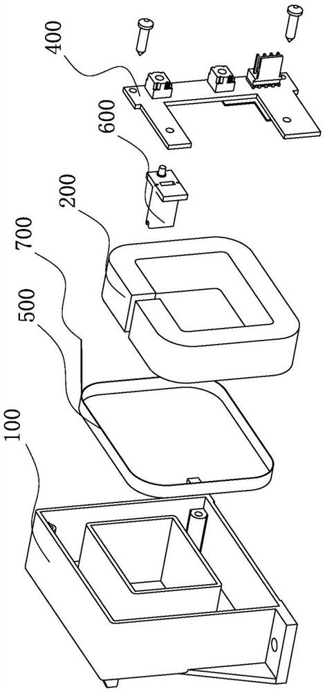
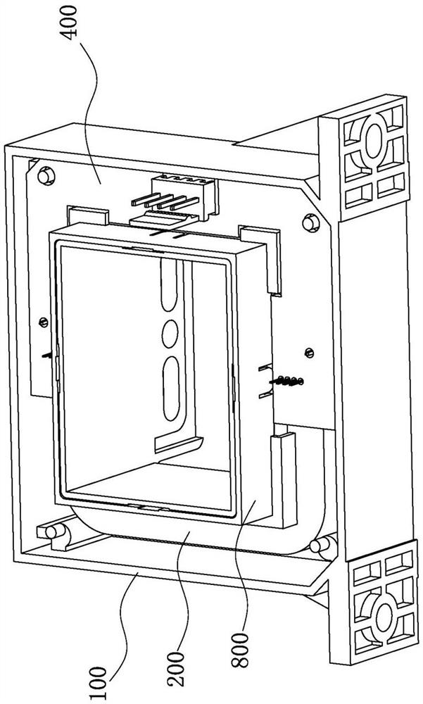
[0067] Such as Figure 3 to Figure 8 As shown, the difference between this embodiment and the first embodiment is that the iron core 200 in this embodiment is a whole, while the iron core 200 in the first embodiment is two oppositely arranged splits .

[0068] It should be noted that, in the present invention, descriptions involving "first", "second", "one" and so on are only for descriptive purposes, and should not be understood as indicating or implying their relative importance or implicitly indicating The number of technical characteristics. Thus, the features defined as "first" and "second" may explicitly or implicitly include at least one of these features. In the description of the present invention, "plurality" means at least two, such as two, three, etc., unless otherwise specifically defined. The terms "connection" and "fixation" should be understood in a broad sense, for example, "fixation" can be a fixed connection, a detachable connection, or an integral body; ...


PUM


Abstract

The invention provides an open-loop Hall current sensor, and belongs to the technical field of sensors, and the open-loop Hall current sensor comprises a housing which is provided with a concave cavity, wherein each corner of the concave cavity is provided with a connecting column; two iron cores, wherein an air gap is formed between the opening ends of the two iron cores, and the two iron cores are embedded in the concave cavity; two fixing pieces connected to the air gap of the iron core respectively through laser welding, wherein notches corresponding to the air gap in position and pins extending outwards are arranged on the fixing pieces; and a main circuit printed board, wherein the iron core is covered with the main circuit printed board, the main circuit printed board and the pins are welded and fixed, and connecting holes fixedly connected with the corresponding connecting columns in an inserted mode are formed in all corners of the main circuit printed board. According to the invention, through the fixing piece, the air gap spacing on the iron core is ensured to be constant, the grounding of the iron core is realized, and the problems of many assembly parts, complex assembly, easy breakage and the like in the prior art are solved, so that the assembly efficiency and the reliability of current signal detection are improved.

Description

technical field [0001] The invention belongs to the technical field of sensors and relates to an open-loop Hall current sensor. Background technique [0002] Traditional open-loop Hall current sensors currently on the market, such as figure 1 and figure 2 As shown, it includes a casing 100, an iron core 200, a sheath 600, a double-lead copper foil tape 500, and a main circuit printed board 400, wherein the sheath 600 is inserted into the air gap 210 of the iron core 200 and fixed with colloid, and then Nest the double-lead copper foil tape 500 on the iron core 200, then embed the iron core 200 in the casing 100, then electrically connect the double-lead copper foil tape 500 and the main circuit printed board 400 through the shielded wire 700, and finally connect the main circuit The printed circuit board 400 is fixed on the housing 100 . However, the above-mentioned open-loop Hall current sensor has the following defects: First, due to the large number of components of...

Claims


Application Information

Patent Timeline
Patent Type & Authority Applications(China)
IPC IPC(8): G01R19/00
CPCG01R19/00
Inventor 叶柳凯胡冬青马华超朱文琴徐钉胡玄张文江吴如兆
Owner NINGBO CRRC TIMES TRANSDUCER TECH CO LTD
Why Eureka
Try Eureka