Improved heat storage system

A heat storage and storage container technology, applied in the direction of electric energy storage systems, indirect heat exchangers, heat exchanger types, etc., can solve expensive and other problems

Inactive Publication Date: 2013-01-09
ENERGY TECH INST
View PDF8 Cites 19 Cited by
  • Summary
  • Abstract
  • Description
  • Claims
  • Application Information

AI Technical Summary

Problems solved by technology

This has the best heat transfer, but the storage substances mus...

Method used


Image

  • Improved heat storage system
  • Improved heat storage system
  • Improved heat storage system

Examples


Embodiment Construction

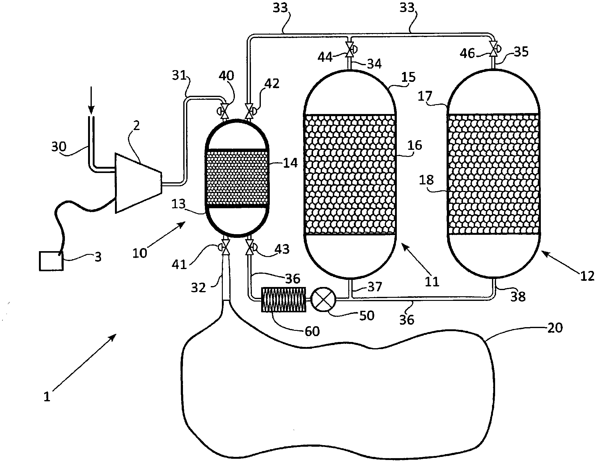
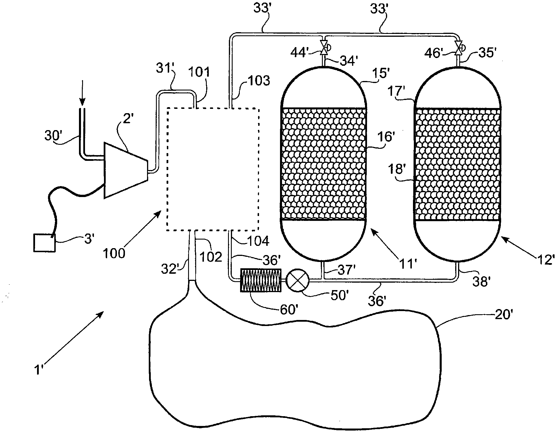
[0134] figure 1 An electrical storage system 1 is shown comprising a compressor / expander (eg compressor / expander turbine) 2 and a gas storage 20 powered by a power source 3 and connected to a high pressure thermal storage 10 . The high-pressure thermal store 10 is in turn connected to low-pressure thermal stores 11 and 12 . Air enters and leaves the system through duct 30 and passes via ducts 31 , 32 , 33 , 34 , 35 , 36 , 37 and 38 . Valves 40, 41, 42, 43, 44 and 46 can be used to selectively close / open the different conduits. An air pump 50 is connected to conduit 36 ​​and can pump air in either direction. Heat exchanger 60 is used to maintain the temperature of the gas passing through conduit 36 ​​at substantially ambient temperature or a fixed base temperature.

[0135] The high-pressure thermal store 10 comprises an insulated high-pressure vessel 13 with a thermal matrix 14 through which the compressed gas can pass and transfer its heat when inflated and from which it r...


PUM


Abstract

Apparatus (1) for storing energy, comprising: a high pressure storage vessel (10) for receiving high pressure gas, the high pressure storage vessel (10) comprising high pressure heat storage means comprising a first chamber housing a first gas-permeable heat storage structure (14); and a low pressure storage vessel (11,12) for receiving low pressure gas, the low pressure storage vessel (11,12) comprising low pressure heat storage means comprising a second chamber housing a second gas-permeable heat storage structure (16,18); wherein the first heat storage structure (14) has a mean surface area per unit volume which is higher than a mean surface area per unit volume of the second heat storage structure (16,18).

Description

technical field [0001] The present invention relates to energy storage devices and in particular, but not exclusively, to devices for receiving and returning energy in electrical form (hereinafter referred to as "electrical storage" devices). Background technique [0002] There are many electrical storage systems that store the heat of compressed air and absorb the work done by the expansion of the air. [0003] An often mentioned example of this is called adiabatic CAES, in which salt caverns are typically used as compressed air storage. When electricity is to be stored, the engine drives a compressor that compresses air into the cavity. The compression process raises the temperature of the air, and for efficient energy recovery it is necessary to store this "heat of compression" with some form of thermal storage. [0004] The cavity is normally kept at a minimum pressure, say 40 bar, which increases to a higher limit, say 60 bar, during inflation. These pressures have t...

Claims


Application Information

Patent Timeline
IPC IPC(8): F01K3/00F01K3/12F02C6/16F02G1/044F03G7/04F23L15/02F28D17/00F28D17/04F28D19/00F28D19/02
CPCF01K3/12Y02E60/15F22B1/006F28D17/04H02J15/006F02D41/005Y02T10/47F28D17/005F02C6/16H02J2310/46Y02E60/16Y02T10/40
Inventor 乔纳森·塞巴斯蒂安·豪斯詹姆斯·麦克纳斯滕
Owner ENERGY TECH INST
Why Eureka
Try Eureka