TBM (tunnel boring machine) bidirectional rotary tapping cutter head and production process thereof

A technology of bidirectional rotation and manufacturing process, applied in mining equipment, earth-moving drilling, tunnels, etc., can solve the problems of large stratum disturbance, difficulty in correcting deviation, affecting the driving speed, etc., to reduce the number of abnormal shutdowns, convenient assembly and maintenance, The effect of improving the driving efficiency

Active Publication Date: 2014-09-17
中铁工程装备集团盾构制造有限公司
View PDF8 Cites 0 Cited by
  • Summary
  • Abstract
  • Description
  • Claims
  • Application Information

AI Technical Summary

Problems solved by technology

[0004] In order to solve the problems of TBM machine jamming, host rolling and excavation deviation from the design axis during the excavation process, the present invention proposes a single-shield TBM cutterhead bidirectional rotating slag discharge construction technology, the purpose of which is to improve the single-shield TBM's deflection correction and anti-rolling capabilities, thereby improving the single-shield TBM's adaptability to geology

Method used


Image

  • TBM (tunnel boring machine) bidirectional rotary tapping cutter head and production process thereof
  • TBM (tunnel boring machine) bidirectional rotary tapping cutter head and production process thereof
  • TBM (tunnel boring machine) bidirectional rotary tapping cutter head and production process thereof

Examples


Embodiment 1

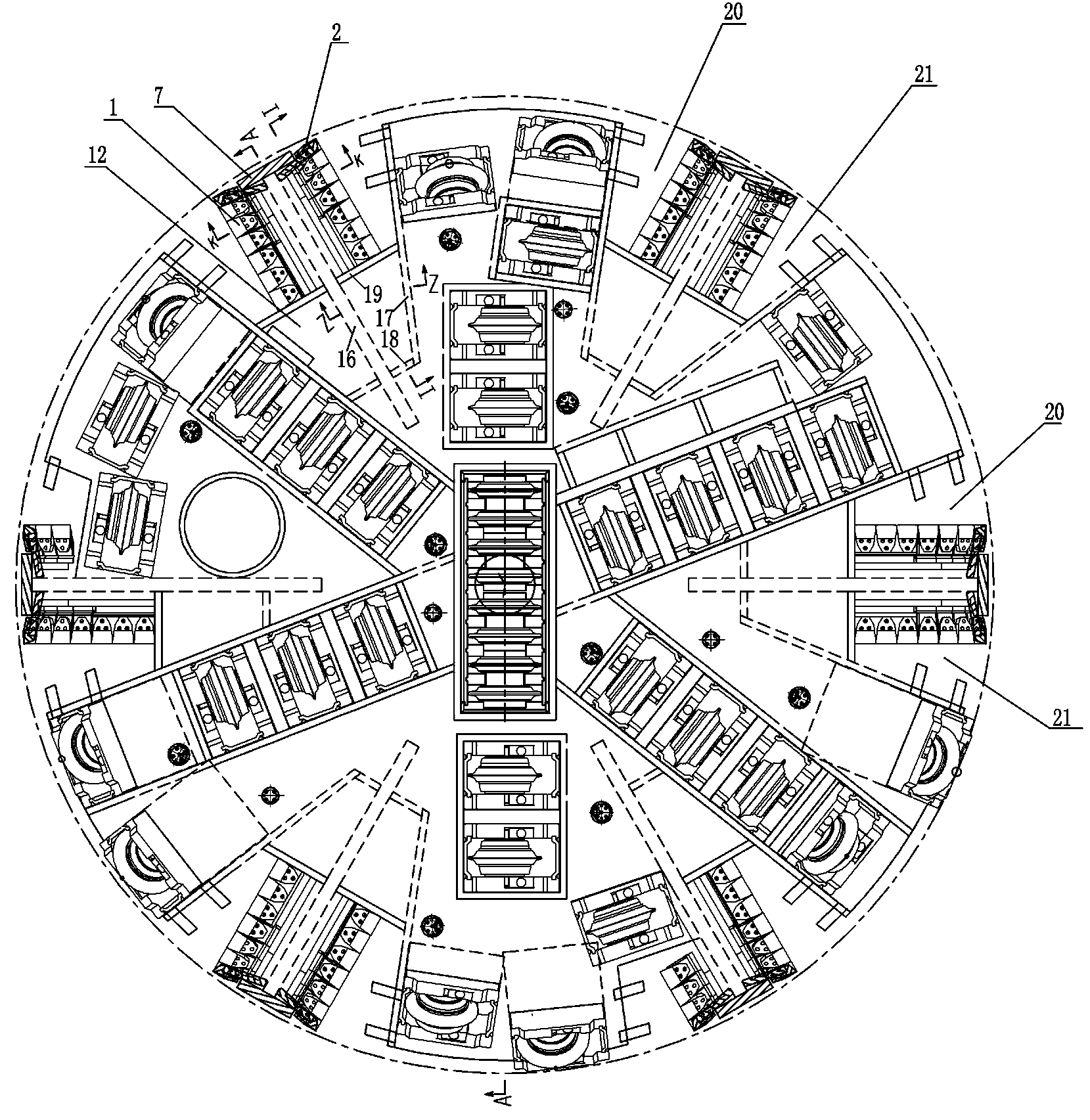
[0039] Embodiment 1: A kind of TBM two-way rotating slag cutter head, see figure 1 , 6 pairs of slag inlets are evenly distributed on the circumference edge of the disc body 12 of the cutter head assembly, which are 6 positive rotation slag inlets 20 and 6 reverse rotation slag inlets 21 respectively.

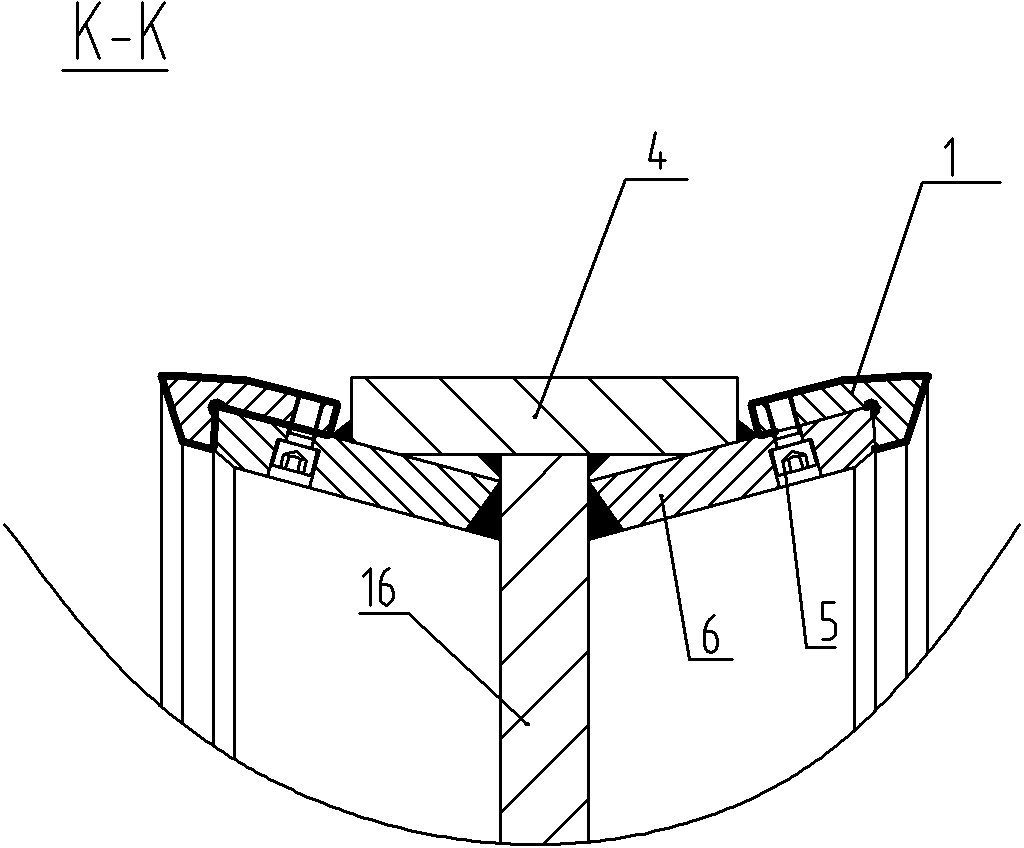
[0040] The middle part of each pair of slag inlets is provided with a slag sliding board 16 , and the slag sliding board 16 is arranged radially and welded on the inner wall of the disc body 12 . Every pair of slag inlets takes the slag sliding plate 16 as the center of symmetry. When the disc body 12 rotates in the forward direction, the 6 forward rotation slag inlets 20 work, and when the disc body 12 rotates in the reverse direction, the 6 reverse rotation slag inlets 21 work.

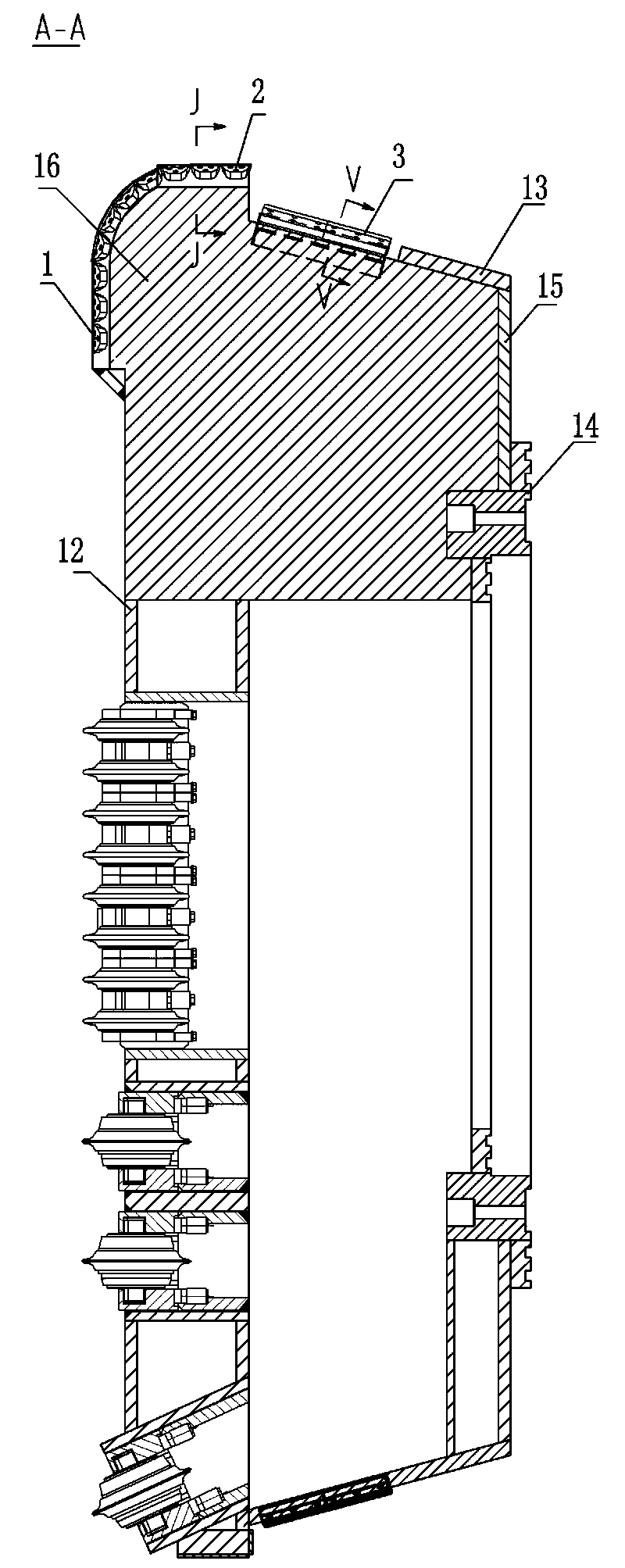
[0041] The upper end and the peripheral area of ​​the slag sliding board 16 slightly exceed the outer edge of the disc body 12 respectively, the upper end of the slag sliding board is a straight se...

Embodiment 2

[0047] Example 2: see Figure 1 to Figure 7 , a TBM two-way rotating slag cutter head manufacturing process, comprising the following steps:

[0048] (1) There are 6 slag inlets evenly distributed around the edge of the disc body 12 of the cutter head assembly, and 6 slag sliding plates 16, 6 conical plates 13, 6 bottom cover plates 15 and 1 bottom Connection flange. Pre-assemble the slag slag plate 16, the conical plate 13, the bottom cover plate 15 and the connecting flange 14 respectively, and check the key dimensions at the same time to ensure accurate assembly positioning; the assembly relationship is as follows:

[0049] Slag sliding plate 16: a slag sliding plate is installed in the middle of the above six slag inlets in the radial direction, and a positive rotation slag inlet and a reverse rotation slag inlet are respectively formed on both sides of each slag sliding board. The upper end of the slag sliding board is a straight section, and the outer side of the slag ...


PUM

PropertyMeasurementUnit
angleaaaaaaaaaa

Abstract

The present invention proposes a TBM two-way rotating slag discharge cutter head and its manufacturing process. The cutter head is evenly distributed with 6 pairs of slag inlets, 6 for forward rotation and 6 for reverse rotation. The size of the slag inlet is appropriate and the position is reasonable. . The slag chute is arranged in the middle of the slag inlet, and the scrapers are symmetrically arranged on the upper part and the surrounding area of ​​the slag chute, and the slag guide groove is arranged at the contact part between the slag chute and the disc body, and the excavated slag passes through the scraper, the slag guide groove, the slag guide The slag slab slips into the slag hopper and is conveyed out by a belt conveyor. The invention improves the deviation-correcting and anti-rolling capabilities of the single-shield TBM, thereby improving the adaptability of the single-shield TBM to geology.

Description

technical field [0001] The invention belongs to the construction technology of mountain tunnels, and in particular relates to the construction technology of single-shield TBM cutterhead bidirectional rotation slag discharge. Background technique [0002] At present, TBM is mainly used as hard rock tunnel boring machine, which is mainly divided into three types: open type, single shield type and double shield type. The open TBM is generally used for temporary non-segment lining tunnel boring machines. The shield outside the machine supports the stone until the lining is completed, and the excavation and segment lining can be carried out simultaneously. Single-shield and double-shield TBMs are used for segment lining tunnel boring machines, and the operation mode is rotary: when segment lining is required, the tunnel boring machine needs to stop. [0003] The current three types of TBM cutter heads are all designed in a single direction of rotation. Since the TBM cutterhead ...

Claims


Application Information

Patent Timeline
Patent Type & Authority Patents(China)
IPC IPC(8): E21D9/08
Inventor 张宁川卓兴建谭顺辉郑康泰张世展蒙先君王纯亮
Owner 中铁工程装备集团盾构制造有限公司
Why Eureka
Try Eureka