Combined type hydraulic cylinder with floating cylinder barrel

A combined, hydraulic cylinder technology, applied in the direction of fluid pressure actuation devices, etc., can solve the problem that the hydraulic cylinder is difficult to meet the requirements of use

Inactive Publication Date: 2015-04-15
ARCHITECTURAL ENG INST GENERAL LOGISTICS DEPT P L A
View PDF7 Cites 0 Cited by
  • Summary
  • Abstract
  • Description
  • Claims
  • Application Information

AI Technical Summary

Problems solved by technology

Ordinary single-cylinder, cylinder-rod hydraulic cylinders are difficult to meet the requirements of use

Method used


Image

  • Combined type hydraulic cylinder with floating cylinder barrel
  • Combined type hydraulic cylinder with floating cylinder barrel
  • Combined type hydraulic cylinder with floating cylinder barrel

Examples


Embodiment Construction

[0018] The present invention is described in further detail below in conjunction with accompanying drawing:

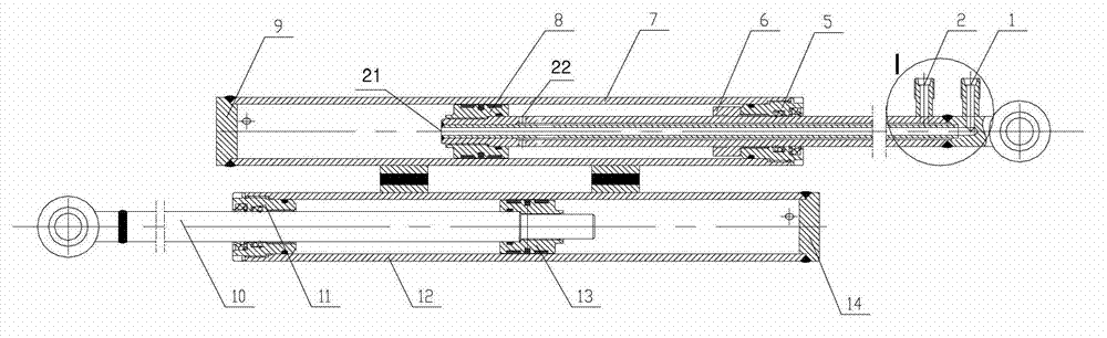
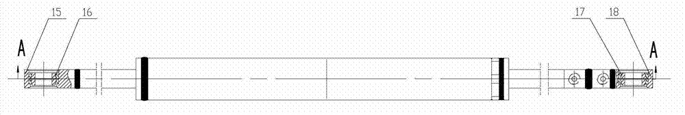
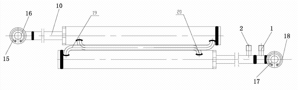
[0019] see Figure 1-6 , the combined hydraulic cylinder with floating cylinder, including the oil inlet piston rod, the combined cylinder and the non-oil inlet piston rod; the combined cylinder includes the oil inlet cylinder 7, the non oil inlet cylinder barrel 12, large cavity oil pipe 19 and small cavity oil pipe 20; the piston rod of the oil inlet end and the piston rod of the non-oil inlet end are respectively combined with the oil inlet end cylinder 7 and the non-oil inlet end cylinder 12 to form the oil inlet hydraulic cylinder and It is not a hydraulic cylinder at the oil inlet end, and the piston rod at the oil inlet end is provided with a large cavity oil port 21 and a small cavity oil port 22, wherein the large cavity oil port 21 is connected to the large cavity of the oil inlet cylinder 7, and the small cavity oil port 22 The small chamber connected to th...


PUM


Abstract

The invention discloses a combined type hydraulic cylinder with a floating cylinder barrel. The combined type hydraulic cylinder comprises an oil inlet end piston rod, a combined type cylinder barrel and a non-oil inlet end piston rod, wherein the oil inlet end piston rod and the non-oil inlet end piston rod are respectively combined with an oil inlet end cylinder barrel and a non-oil inlet end cylinder barrel to form an oil inlet end hydraulic cylinder and a non-oil inlet end hydraulic cylinder; a large cavity oil port and a small cavity oil port which are respectively communicated with a large cavity and a small cavity of the oil inlet end cylinder barrel are respectively formed in the oil inlet end piston rod; a large cavity oil pipe is communicated with the large cavities of the oil inlet end cylinder barrel and the non-oil inlet cylinder barrel; and a small cavity oil pipe is communicated with the small cavities of the oil inlet end cylinder barrel and the non-oil inlet cylinder barrel. According to the combined type hydraulic cylinder with the floating cylinder barrel, the design of the hydraulic oil cylinders is optimized, so that two hydraulic oil cylinders with relatively small travels are connected in series with each other; by a mode of feeding oil through cylinder rods, the combined type hydraulic cylinder can telescopically move in two directions; an oil cylinder telescopic amount with relatively high amplitude is realized when a mounting size is relatively small; and therefore, a telescopic amount which is one time higher than that of the common hydraulic cylinder can be realized.

Description

technical field [0001] The invention belongs to the field of construction machinery and relates to a hydraulic cylinder, in particular to a combined hydraulic cylinder with a floating cylinder barrel. Background technique [0002] With the wide application of hydraulic technology, the performance requirements for hydraulic products are getting higher and higher, and the performance requirements for actuator hydraulic cylinders are also getting higher and higher. In places such as forklift side shifters that require built-in hydraulic cylinders, and require relatively high strokes of hydraulic cylinders, but the installation space is limited, the demand for special hydraulic cylinders is relatively strong. Ordinary hydraulic cylinders with single cylinder and cylinder rod structure are difficult to meet the requirements of use. Contents of the invention [0003] The object of the present invention is to overcome the above-mentioned shortcoming of prior art, provide a kind ...

Claims


Application Information

Patent Timeline
Patent Type & Authority Patents(China)
IPC IPC(8): F15B15/08
Inventor 徐磊朱从民王卫国巩万锋房月根李璐宋昆王卫青俞汉生
Owner ARCHITECTURAL ENG INST GENERAL LOGISTICS DEPT P L A
Why Eureka
Try Eureka