Check patentability & draft patents in minutes with Patsnap Eureka AI!

Radiating device

A technology of heat dissipation device and heat dissipation fin set, which is applied in indirect heat exchangers, lighting and heating equipment, cooling/ventilation/heating renovation, etc., can solve the problems of limited thermal contact area and unsatisfactory heat dissipation effect, and achieve good heat dissipation effect of effect

Inactive Publication Date: 2013-01-23
HONG FU JIN PRECISION IND (SHENZHEN) CO LTD +1
View PDF0 Cites 0 Cited by
  • Summary
  • Abstract
  • Description
  • Claims
  • Application Information

AI Technical Summary

Problems solved by technology

However, the existing heat dissipation fins are often only connected to the heat conduction pipe, the thermal contact area is limited, and the heat dissipation effect is not ideal

Method used


Image

  • Radiating device
  • Radiating device
  • Radiating device

Examples


Embodiment Construction

[0021] The embodiment of the present invention relates to a heat dissipation device, which can be applied to electronic devices, such as desktop computers, servers, etc., to dissipate heat from heat-generating electronic components. The heat dissipation device can be used in conjunction with other auxiliary heat dissipation elements, such as a wind guide cover, a fan, etc., to achieve better heat dissipation effects.

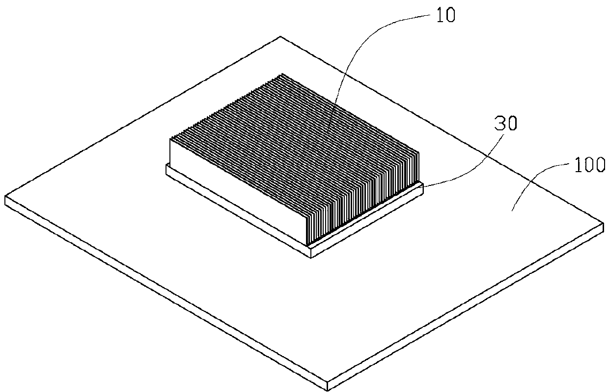
[0022] see figure 1 , in one embodiment, a heat dissipation device can be installed on a computer motherboard 100 for dissipating heat from a heating element 110 . The heating element 110 can be a CPU, a south bridge chip, a north bridge chip and the like. The heat dissipation device includes a heat dissipation fin set 10 , a base 30 and a heat pipe 50 mounted on the base 30 .

[0023] The base 30 is flat. The base 30 can be rectangular. The base 30 includes a first contact surface 31 for contacting the heating element 110 and a second contact surface 33 opp...


PUM


Abstract

The invention discloses a radiating device, comprising a base and a radiating fin group, wherein the substrate is used for contacting with heating elements; the base is of a flat plate shape and comprises a first contact surface and a second contact surface, wherein the first contact surface is used for contacting with the heating elements, and the second contact surface is opposite to the first contact surface; the base is provided with a groove at one side of the second contact surface; the radiating device further comprises a heat pipe, wherein the heat pipe is located in the groove; and the radiating fin group simultaneously contacts with the second contact surface of the base and the heat pipe. According to the radiating device, as the radiating fin group simultaneously contacts with the second contact surface of the base and the heat pipe, the relatively good radiating effect can be realized.

Description

technical field [0001] The invention relates to a heat dissipation device, in particular to a heat dissipation device for contacting electronic components to dissipate heat. Background technique [0002] Existing heat dissipation devices for electronic components are generally provided with radiators on electronic components. Radiators generally include bases, heat dissipation fins, and heat conduction pipes inserted into the heat dissipation fins and connected to the base. The upper part of the heat dissipation fins or The cooling fan is fixed on the side. The heat sink has good thermal conductivity, and the heat generated by the electronic components is conducted to the heat dissipation fins by the heat conduction tube. The airflow generated by the cooling fan quickly takes the heat away from the cooling fins, so as to achieve the purpose of dissipating heat and cooling electronic components. However, the existing heat dissipation fins are often only connected to the hea...

Claims


Application Information

Patent Timeline
Patent Type & Authority Applications(China)
IPC IPC(8): H01L23/427H05K7/20
CPCH01L23/433H01L23/427F28D15/0233F28D15/0275H01L2924/0002H01L2924/00
Inventor 黄国和
Owner HONG FU JIN PRECISION IND (SHENZHEN) CO LTD
Features
  • R&D
  • Intellectual Property
  • Life Sciences
  • Materials
  • Tech Scout
  • Unparalleled Data Quality
  • Higher Quality Content
  • 60% Fewer Hallucinations
Learn More