Micro-electro-mechanical comb tooth mechanism capable of adjusting tooth gaps by electrostatic force

A tooth gap and electrostatic force technology, applied in the field of micro-electromechanical system structure, can solve the problems of wasting driving force, weak sensing detection signal, and increased gap, so as to increase the amplitude of sensing detection signal, increase detection sensitivity, The effect of expanding the scope of application

Inactive Publication Date: 2015-03-04
SOUTHEAST UNIV
View PDF9 Cites 0 Cited by
  • Summary
  • Abstract
  • Description
  • Claims
  • Application Information

AI Technical Summary

Problems solved by technology

Since the gap between the comb teeth of the traditional structure is immutable and cannot be made very small due to the limitation of the process, the sensing detection signal generated by the micro-electromechanical vibration is also very weak
[0004] Some researchers have proposed a comb structure with adjustable gaps on one side, but this structure has the following two main disadvantages: because the comb teeth are usually a multi-pair structure, the reduction of the gap on one side will inevitably lead to the increase of the gap on the other side, which is wasteful. The driving force on one side; because the gap between the two sides of the movable tooth is asymmetrical, the magnitude of the electrostatic force between the movable tooth and the fixed teeth on both sides is different, and the one-dimensional linear motion of the movable tooth will be affected, resulting in two-dimensional motion

Method used


Image

  • Micro-electro-mechanical comb tooth mechanism capable of adjusting tooth gaps by electrostatic force
  • Micro-electro-mechanical comb tooth mechanism capable of adjusting tooth gaps by electrostatic force
  • Micro-electro-mechanical comb tooth mechanism capable of adjusting tooth gaps by electrostatic force

Examples


Embodiment Construction

[0024] The present invention will be further described below in conjunction with the accompanying drawings.

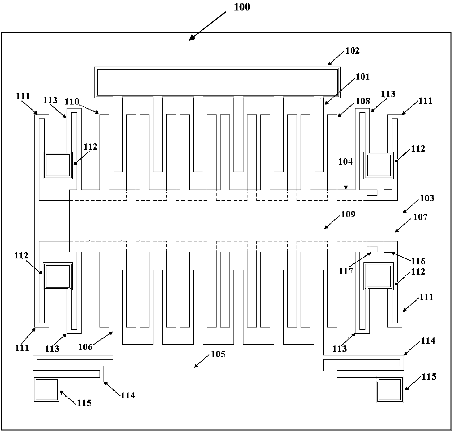
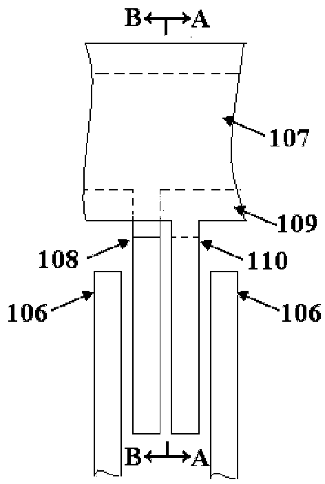
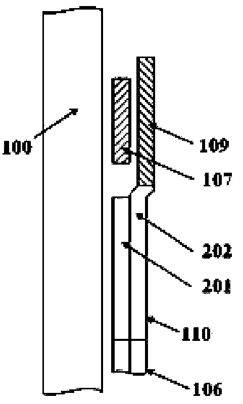
[0025] Such as Figure 1 to Figure 4 As shown, a micro-electromechanical comb tooth mechanism of the present invention that modulates the tooth gap by electrostatic force includes electrostatic driving teeth, fixed teeth consisting of left-moving fixed teeth 103 and right-moving fixed teeth 104, movable teeth, four first Anchor region 112 and insulating substrate 100 . The four first anchor regions 112 are respectively fixedly connected to the insulating substrate 100 . The left-moving fixed tooth 103 includes a first wide beam 107 , a left-moving comb tooth 108 , and four first folded beams 111 bent along the transverse direction. When the first folded beam 111 bent along the transverse direction moves, it can only move along the transverse direction. The left-moving comb teeth 108 are fixed on both sides of the first wide beam 107 . Both ends of the first wide be...


PUM


Abstract

The invention discloses a micro-electro-mechanical comb tooth mechanism capable of adjusting tooth gaps by electrostatic force. The mechanism comprises an electrostatic drive tooth, a fixed tooth consisting of a leftward movement fixed tooth and a rightward movement fixed tooth, a movable tooth, first anchor areas, and an insulation substrate; the first anchor areas are fixedly connected with the insulation substrate; the leftward movement fixed tooth comprises a first wide beam, leftward movement comb teeth and four first folding beams which are bent in a horizontal direction; the rightward movement fixed tooth comprises a second wide beam, rightward movement comb teeth, and four second folding beams which are bent in a horizontal direction; the electrostatic drive tooth comprises comb teeth and a third anchor area; the leftward movement comb teeth, the comb teeth and the leftward movement comb teeth are sequentially and alternatively distributed; the movable tooth comprises a mass block, movable tooth comb teeth, second anchor areas and third folding beams which are bent in a longitudinal direction; the rightward movement comb teeth, the movable tooth comb teeth and the leftward movement comb teeth are sequentially and alternatively distributed; and the first wide beam is provided with a leftward movement stop block; and the second wide beam is provided with a rightward movement stop block. The micro-electro-mechanical comb tooth mechanism adjusts the tooth gaps under the drive of electrostatic force, so that strong signals are produced by micro-electro-mechanical vibration.

Description

technical field [0001] The invention belongs to the technical field of micro-electro-mechanical system structure, and in particular relates to a micro-electro-mechanical comb mechanism for adjusting the gap between teeth by electrostatic force. Background technique [0002] Comb structures are widely used in MEMS, for example, resonators, accelerometers, angular velocity meters, gyroscopes, etc. The traditional comb structure consists of paired fixed teeth and movable teeth. The fixed teeth and movable teeth are arranged at intervals and usually have many pairs. In the traditional structure, the fixed teeth remain in a static state without longitudinal and lateral displacement, while the movable teeth usually move in the form of vibration under the action of external force, and the direction of motion is along the length of the teeth. [0003] Due to the limitation of machining accuracy, the gap between the fixed tooth and the movable tooth in the comb tooth structure canno...

Claims


Application Information

Patent Timeline
Patent Type & Authority Patents(China)
IPC IPC(8): B81B3/00
Inventor 李伟华浦烜周再发黄庆安
Owner SOUTHEAST UNIV
Why Eureka
Try Eureka