Micro electro mechanical (MEM) comb tooth mechanism capable of modulating backlash under electromagnetic drive

A technology of electromagnetic drive and tooth gap, which is applied in the direction of microstructure devices composed of deformable components, microstructure technology, microstructure devices, etc., can solve the problems of wasted driving force, increased gap, weak sensor detection signal, etc. question

Inactive Publication Date: 2015-04-15
SOUTHEAST UNIV
View PDF6 Cites 0 Cited by
  • Summary
  • Abstract
  • Description
  • Claims
  • Application Information

AI Technical Summary

Problems solved by technology

Since the gap between the comb teeth of the traditional structure is immutable and cannot be made very small due to the limitation of the process, the sensing detection signal generated by the micro-electromechanical vibration is also very weak
[0004] Some researchers have proposed a comb structure with adjustable gaps on one side, but this structure has the following two main disadvantages: because the comb teeth are usually a multi-pair structure, the reduction of the gap on one side will inevitably lead to the increase of the gap on the other side, which is wasteful. The driving force on one side; because the gap between the two sides of the movable tooth is asymmetrical, the magnitude of the electrostatic force between the movable tooth and the fixed teeth on both sides is different, and the one-dimensional linear motion of the movable tooth will be affected, resulting in two-dimensional motion

Method used


Image

  • Micro electro mechanical (MEM) comb tooth mechanism capable of modulating backlash under electromagnetic drive
  • Micro electro mechanical (MEM) comb tooth mechanism capable of modulating backlash under electromagnetic drive
  • Micro electro mechanical (MEM) comb tooth mechanism capable of modulating backlash under electromagnetic drive

Examples


Embodiment Construction

[0026] The present invention will be further described below in conjunction with the accompanying drawings.

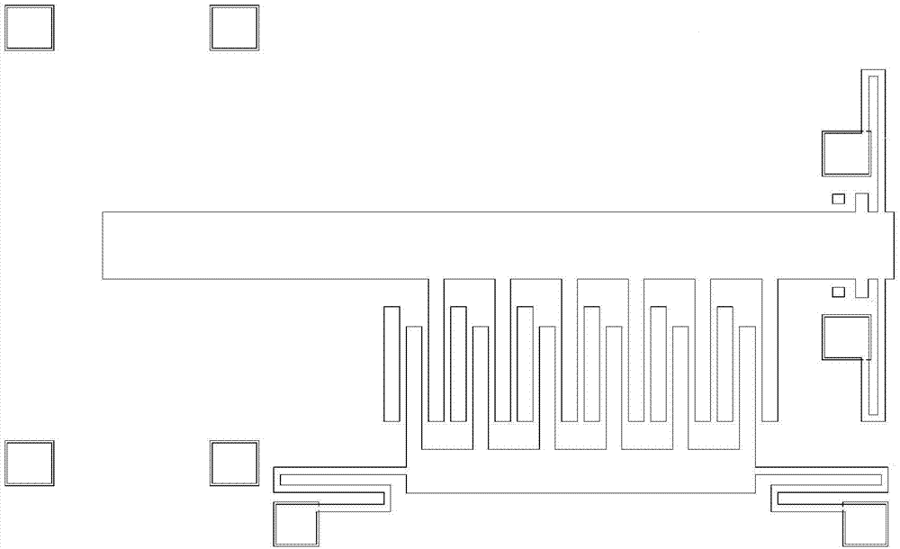
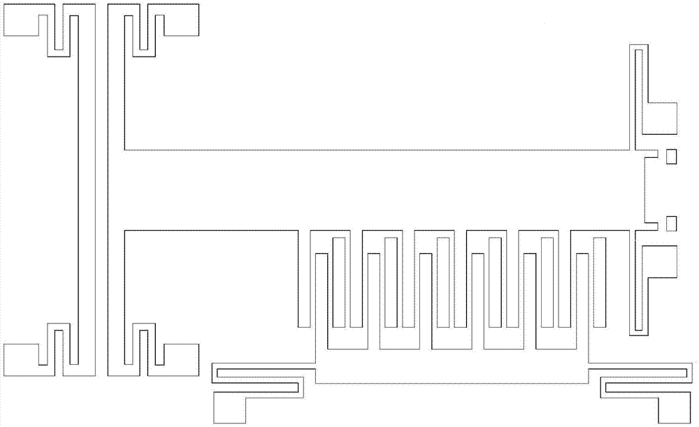
[0027] Such as Figure 1 to Figure 5 As shown, the microelectromechanical comb tooth mechanism of the present invention, which is electromagnetically driven to adjust the tooth gap, includes a left-moving electromagnetic actuator, a right-moving electromagnetic actuator, a fixed tooth consisting of a left-moving fixed tooth 103 and a right-moving fixed tooth 104, a moving teeth, the two first anchor regions 112 and the insulating substrate 100. The left-moving electromagnetic actuator is connected to one end of the left-moving fixed tooth 103 , and the other end of the left-moving fixed tooth 103 is connected to the first anchor area 112 . The right-moving electromagnetic actuator is connected to one end of the right-moving fixed tooth 104 , and the other end of the right-moving fixed tooth 104 is connected to the first anchor area 112 . The left-moving fixed tooth 1...


PUM


Abstract

The invention discloses a micro electro mechanical (MEM) comb tooth mechanism capable of modulating backlash under electromagnetic drive. The MEM comb tooth mechanism capable of modulating the backlash under the electromagnetic drive comprises a left shifting electromagnetic actuator, a right shifting electromagnetic actuator, a fixed tooth, a moving tooth, a first anchoring area and an insulating substrate, wherein the fixed tooth consists of a left shifting fixed tooth and a right shifting fixed tooth; the left shifting electromagnetic actuator is connected with one end of the left shifting fixed tooth; the other end of the left shifting fixed tooth is connected onto the first anchoring area; the right shifting electromagnetic actuator is connected with one end of the right shifting fixed tooth; the other end of the right shifting fixed tooth is connected onto the first anchoring area; the left shifting fixed tooth comprises a first broad beam, a left shifting comb tooth and two first folding beams; the right shifting fixed tooth comprises a second broad beam, a right shifting comb tooth and two second folding beams; the moving tooth comprises a mass block, a moving comb tooth, two second anchoring areas and two third folding beams; the first broad beam is provided with a left shifting check block; and the second broad beam is provided with a right shifting check block. The backlash is modulated by the MEM comb tooth mechanism under the electromagnetic drive, so that signals generated by MEM vibrations are high in strength.

Description

technical field [0001] The invention belongs to the technical field of micro-electro-mechanical system structure, and in particular relates to a micro-electro-mechanical comb mechanism for adjusting tooth gaps by electromagnetic drive. Background technique [0002] Comb structures are widely used in MEMS, for example, resonators, accelerometers, angular velocity meters, gyroscopes, etc. The traditional comb structure consists of paired fixed teeth and movable teeth. The fixed teeth and movable teeth are arranged at intervals and usually have many pairs. In the traditional structure, the fixed teeth remain in a static state without longitudinal and lateral displacement, while the movable teeth usually move in the form of vibration under the action of external force, and the direction of motion is along the length of the teeth. [0003] Due to the limitation of machining accuracy, the gap between the fixed tooth and the movable tooth in the comb tooth structure cannot be smal...

Claims


Application Information

Patent Timeline
IPC IPC(8): B81B3/00
Inventor 李伟华浦烜周再发黄庆安
Owner SOUTHEAST UNIV
Why Eureka
Try Eureka