
Backlight module and display device

A display device and backlight module technology, applied in the direction of lighting devices, fixed lighting devices, components of lighting devices, etc.

Active Publication Date: 2014-12-10
BOE TECH GRP CO LTD +1
View PDF5 Cites 0 Cited by
  • Summary
  • Abstract
  • Description
  • Claims
  • Application Information

AI Technical Summary

Problems solved by technology

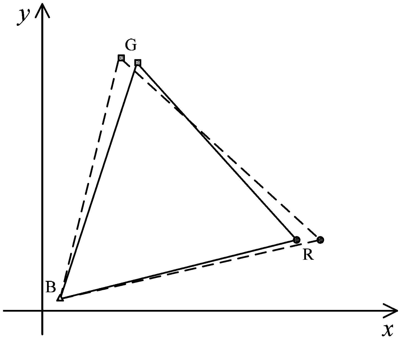
[0003] Although the LED backlight has the above advantages, its color gamut range is only 70%~80% of the standard color gamut

Method used


Image

  • Backlight module and display device
  • Backlight module and display device
  • Backlight module and display device

Examples


Embodiment Construction

[0024] The specific implementation manners of the present invention will be further described in detail below in conjunction with the accompanying drawings and embodiments. The following examples are used to illustrate the present invention, but are not intended to limit the scope of the present invention.

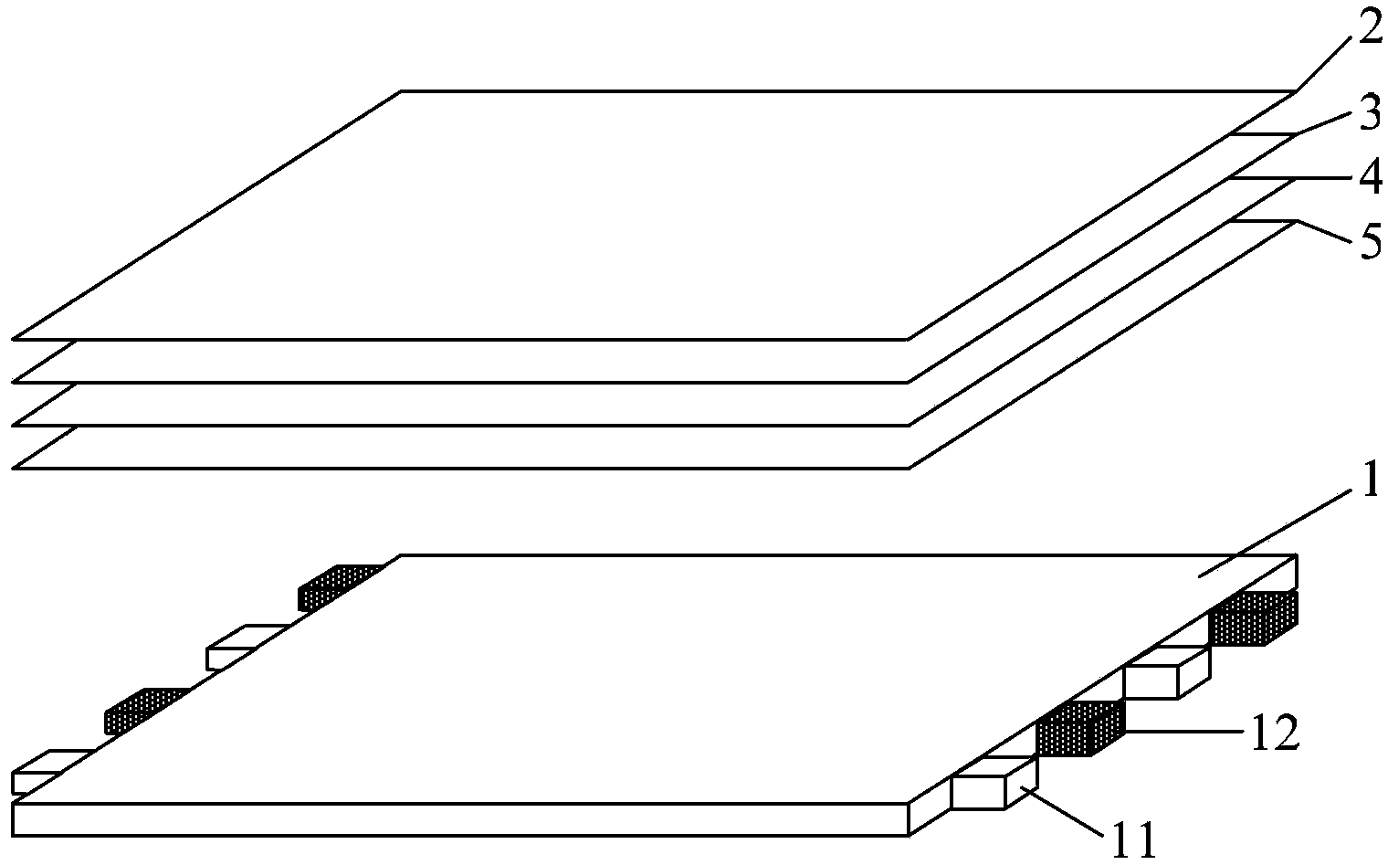
[0025] Such as figure 1 As shown, the structure of the backlight module in this embodiment includes: a light guide plate 1 , a diffusion sheet 2 , a prism sheet 3 , a prism sheet 4 , and a diffusion sheet 5 . There is an LED Bar on both sides of the light guide plate 1, and the LED Bar is provided with a white light source 11 (white-emitting LED) and N primary colors (such as: three primary colors red, green, blue RGB, four primary colors CMYK or other custom color systems) ) monochromatic light source 12 of at least one color. In order to mix the light sources evenly, the white light sources 11 and the monochrome light sources 12 are arranged at intervals.

[0026] The...


PUM


Abstract

The present invention discloses a backlight module, which comprises a light guide plate and a light bar disposed on the light guide plate, wherein white light sources and monochromatic light sources having at least one color of N primitive colors wherein N is greater than or equal to 3. The present invention further discloses a display device comprising such a backlight module. With the present invention, the color gamut range of a light-emitting diode (LED) backlight display system can be widened.

Description

technical field [0001] The invention relates to the field of display technology, in particular to a backlight module and a display device. Background technique [0002] Liquid crystal display devices have become the mainstream of display devices, and are mainly used in liquid crystal displays for computers, large-size LCD TVs, and the like. Since the liquid crystal panel itself cannot emit light, it needs to be used in conjunction with a backlight source to achieve a display effect. In the early stage of liquid crystal display equipment development, the mainstream backlight was CCFL (Cold Cathode Fluorescent Lamp), but the mechanical strength of CCFL was insufficient, the expressiveness of color was not good, and it contained mercury, which did not meet the environmental protection requirements. In recent years, LED backlights have gradually replaced the use of CCFL backlights. It should be because compared with CCFL backlight, LED has many advantages: no toxic substances,...

Claims


Application Information

Patent Timeline
Patent Type & Authority Patents(China)
IPC IPC(8): F21S8/00F21V19/00G02F1/13357F21Y101/02
CPCG02B6/0073G02B6/0068
Inventor 姚树林
Owner BOE TECH GRP CO LTD
Learn More