
Method and system for pre-ignition control

A pre-ignition and cylinder technology, applied in the field of pre-ignition control and system, can solve problems such as increased emissions and fuel economy degradation

Inactive Publication Date: 2016-11-16
FORD GLOBAL TECH LLC
View PDF6 Cites 0 Cited by
  • Summary
  • Abstract
  • Description
  • Claims
  • Application Information

AI Technical Summary

Problems solved by technology

As such, this can lead to an unwanted increase in emissions
Additionally, fuel economy may deteriorate

Method used


Image

  • Method and system for pre-ignition control
  • Method and system for pre-ignition control
  • Method and system for pre-ignition control

Examples


Embodiment Construction

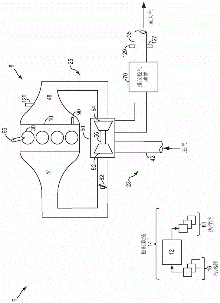
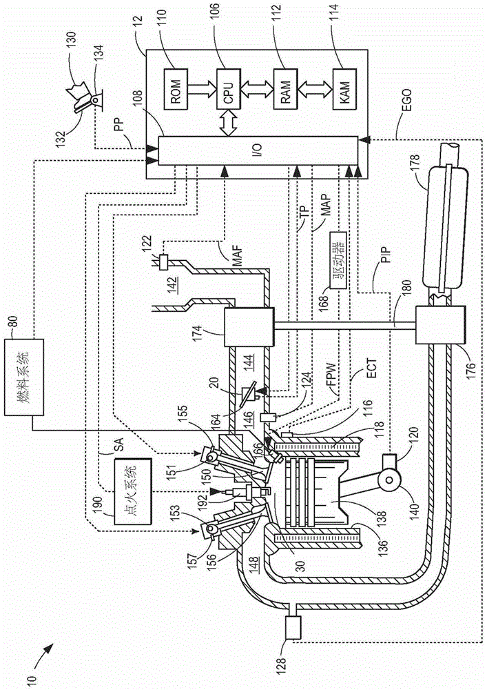
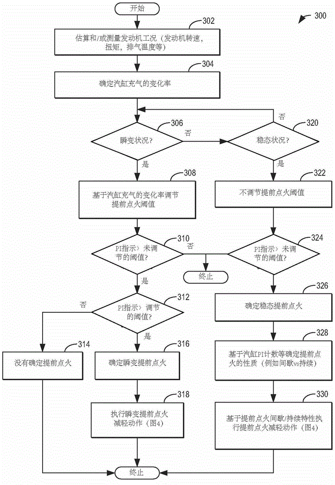
[0017] The following description relates to methods for regulating an engine based on a rate of change of a parameter indicative of cylinder charge (e.g. Figure 1-2 A system and method for detecting and mitigating pre-ignition in an engine system. In this way, severe knock during transient engine conditions may be better distinguished from knock caused by an actual pre-ignition event. The engine controller can be configured to execute control programs such as Figure 3-4 Example routine for ) to adjust cylinder pre-ignition thresholds and pre-ignition mitigation actions (eg, rich and / or load limiting) based on the estimated rate of change of cylinder air charge. reference here Figure 5 An example cylinder operation is illustrated. The engine controller may be further configured to adjust injection (eg, timing, number of injections, split ratio, etc.) of pre-ignition suppression fluid in response to the indication of pre-ignition based on whether the pre-ignition character...


PUM


Abstract

The present invention provides a method for controlling an engine in response to a pre-ignition event. A pre-ignition threshold and a pre-ignition mitigation action are adjusted based on the cylinder charge rate of change. Thus, pre-ignition events occurring during transient engine operating conditions are detected and addressed differently than pre-ignition events during steady-state engine operating conditions.

Description

【Technical field】 [0001] The present invention generally relates to methods and systems for controlling a vehicle engine to reduce the occurrence of pre-ignition. 【Background technique】 [0002] Under certain operating conditions, engines with high compression ratios or boosting to boost specific outputs may be prone to low speed pre-ignition combustion events. Pre-ignition due to pre-ignition can cause very high in-cylinder pressures and can lead to combustion pressure fluctuations similar to combustion knock (but with greater intensity). Strategies have been developed for predicting and / or early detection of pre-ignition based on engine operating conditions. Additionally, after detection, a number of steps to mitigate pre-ignition may be taken. [0003] US patent US2011 / 0139120 shows an example strategy for detecting and mitigating pre-ignition. Therein, pre-ignition is indicated based on knock intensity and timing, and cylinder enrichment is performed in response to th...

Claims


Application Information

Patent Timeline
Patent Type & Authority Patents(China)
IPC IPC(8): F02P5/00
CPCF02D35/02F02D35/021F02D35/023F02D41/0007F02D41/0025F02D41/10F02D41/182F02D41/402F02D41/403F02D35/027Y02T10/12Y02T10/40F02M69/46F02P5/1528
Inventor C·P·格卢格拉M·满斯尼
Owner FORD GLOBAL TECH LLC
Learn More