

Transparent electrode device, information input device, and electronic equipment
A technology of information input device and transparent electrode, which is applied in the direction of transportation and packaging, input/output process of data processing, instruments, etc., can solve problems such as degradation of visual recognition of displayed images, and achieve the goal of preventing display performance, suppressing contrast, and realizing display Effect
- Summary
- Abstract
- Description
- Claims
- Application Information
AI Technical Summary
Problems solved by technology
Method used
Image

Examples
no. 6 approach
[0052] 10. Sixth Embodiment (Display Device Using Information Input Device)
[0053] 11. Seventh Embodiment (Example of Application to Electronic Devices)
[0054] It should be noted that components common to the embodiments will be denoted by the same reference numerals, and repeated description will be omitted.
[0055] 1. First embodiment (a transparent electrode device with the same random pattern provided on the electrode region and the insulating region)
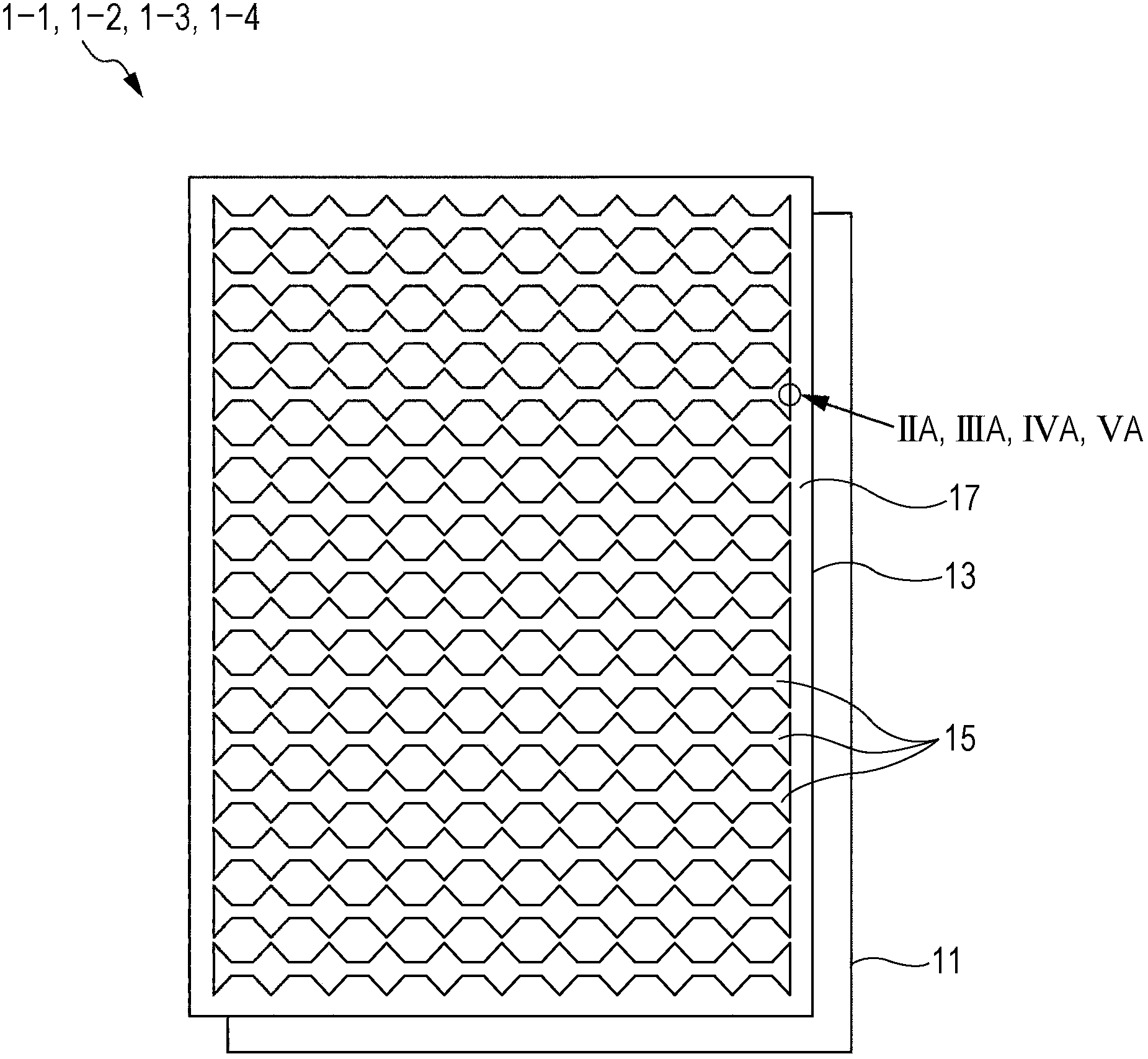
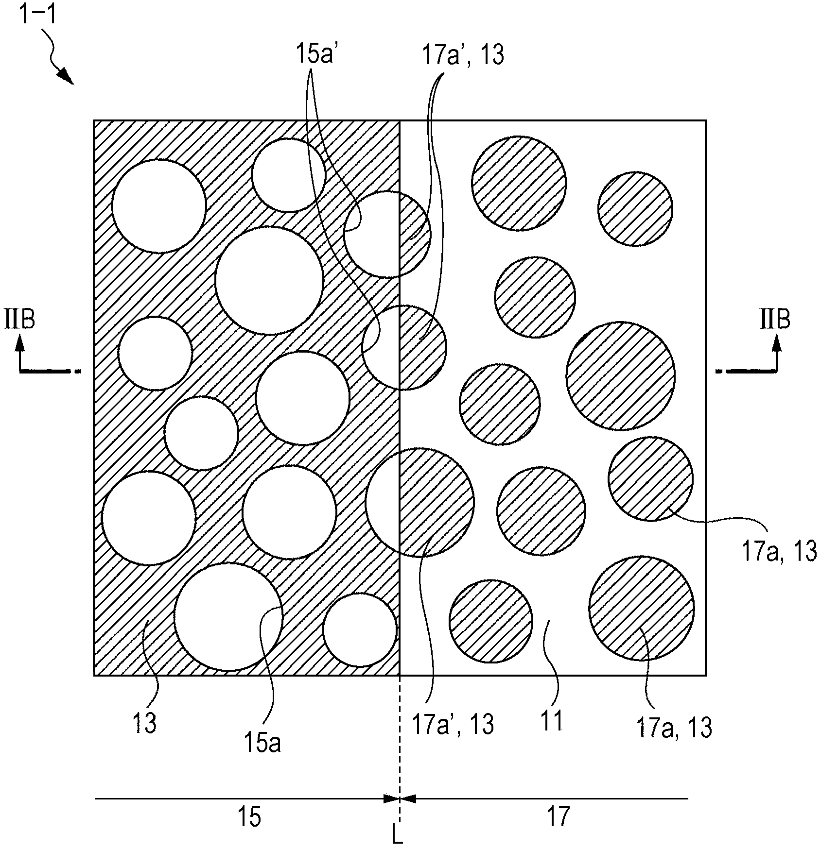
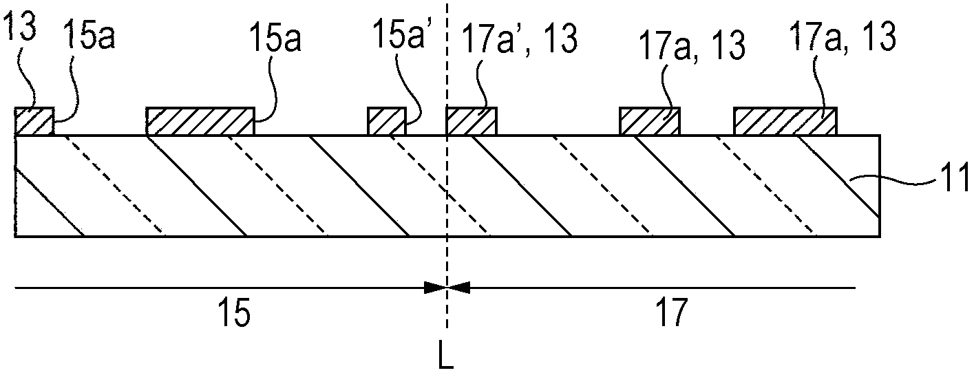
[0056] figure 1 is a plan view for describing the configuration of the transparent electrode device according to the first embodiment. Figure 2A yes figure 1 The enlarged plan view of the enlarged part IIA in , and Figure 2B is along Figure 2A A cross-sectional view taken along line IIB-IIB in . The transparent electrode device 1 - 1 shown in these figures is, for example, a transparent electrode device that is properly placed on the display screen side of the display panel and is configured as follows.
[00...
no. 1 approach
[0082] In particular, island-shaped patterns 17 a having a diameter of 100 μm or more are provided to insulating region 17 . Generally, hole-like patterns and island-like patterns are more easily recognized visually if the size exceeds 100 μm. However, regarding the first embodiment, a pattern having a diameter of 100 μm or more is included as the island-shaped pattern 17 a constituting the insulating region 17 . Thereby, the range of the width (diameter) provided with respect to the random island pattern 17 a can be changed in an increasing direction, and the coverage percentage of the transparent conductive film 13 at the insulating region 17 can be increased. This is also advantageous because, in the case where the island pattern 17a is formed of a ring structure on the order of micrometers or less, generation of moiré can be suppressed.
[0083] Now, Table 1 below shows the pattern diameter, the closest distance between the patterns, and the pattern fill percentage in the...
no. 4 approach
[0118] Regarding the fourth embodiment, the configuration of the insulating region 17 with respect to the electrode region 15-4 in which the transparent conductive film 13 is formed as a solid film is the same as that of the first embodiment, so the percentage of coverage of the transparent conductive film 13 in the insulating region 17 is The setting range is larger than in the first embodiment. Therefore, the diameter range of the island-shaped pattern 17 a arranged in the insulating region 17 is set so as to be larger than the first embodiment including the island-shaped pattern 17 a having a diameter of 100 μm or more.
[0119] Effects of the Fourth Embodiment
[0120] Regarding the above-mentioned transparent electrode device 1-4, the electrode region 15-4 has the transparent conductive film 13 formed as a solid film, but a plurality of island-shaped patterns having a diameter of 100 μm or more are provided to the insulating region 17 in the same manner as the first embod...
PUM
 Abstract
Description
Claims
Application Information