

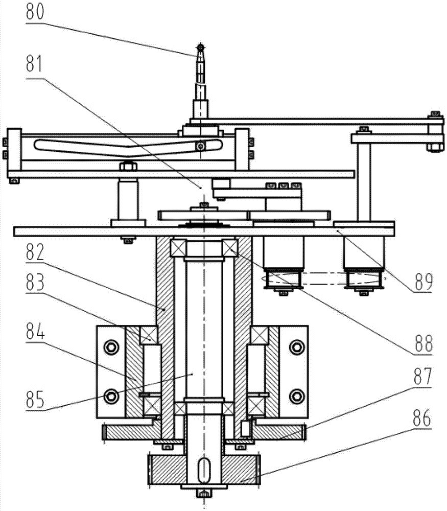
Continuous cable bundling mechanism
A technology of pulling handles and winding handles, which is applied to detonators, offensive equipment, etc., can solve the problems of difficulty in extracting detonators, low work efficiency, and inconvenient use by users, and achieve the effect of low work efficiency and simple structure
- Summary
- Abstract
- Description
- Claims
- Application Information
AI Technical Summary
Problems solved by technology
Method used
Image

Examples
Embodiment Construction
[0011] The present invention will be further described below in conjunction with the accompanying drawings and embodiments.
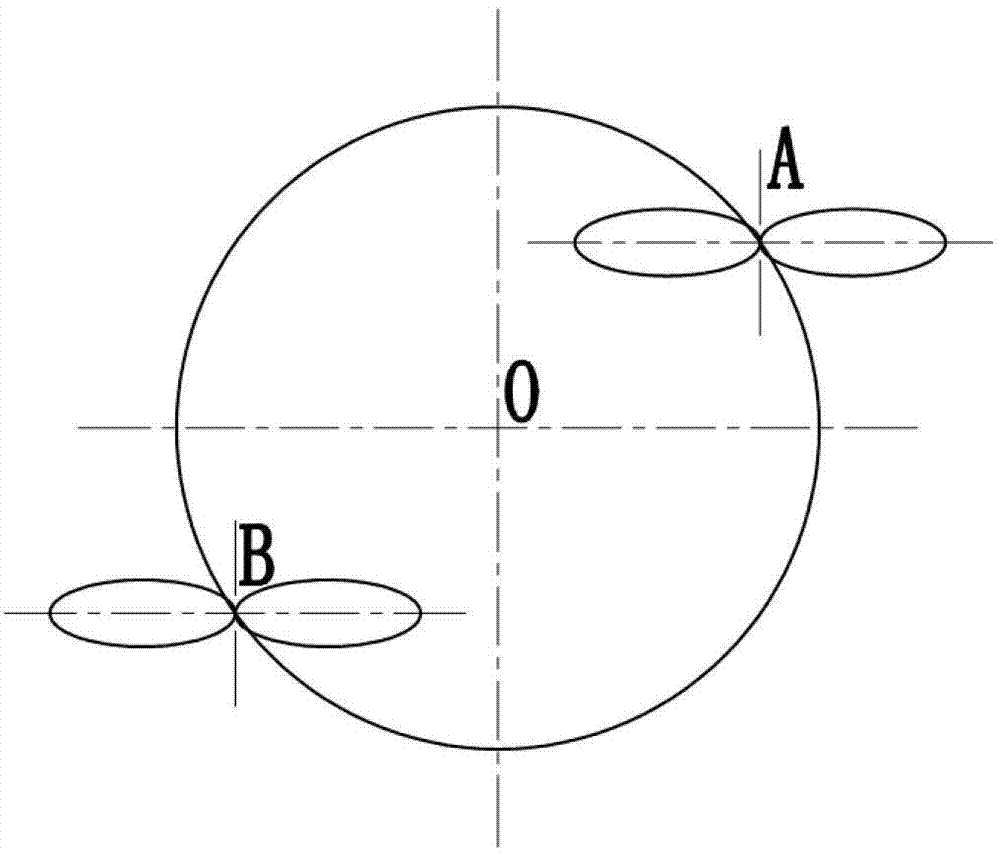
[0012] The present invention provides a continuous handle device with dual stations A and B, which improves the original process steps of handle-waist-cutting-stripping-discharging to complete the handle of the product at station A- At the same time as the tying process, station B completes the cutting-stripping-unloading process of the product at this station, and the handle head makes a circular motion from station A to station B to start the handle-waisting process of the product at this station, A The station completes the product cutting-stripping-unloading process of the station. These two stations go round and round to complete the continuous handle of the thread. This method makes a working cycle from handle-waist-cutting-stripping- The sum of the unloading time is reduced to the sum of the handle-waist time, which not only ensures the technical...
PUM
 Abstract
Description
Claims
Application Information