Bathroom floor components

A bathroom and floor technology, applied in drainage structures, building structures, waterway systems, etc., can solve the problems of loss of travel paths, difficult cleaning, easy pollution, etc., to maintain dry performance, improve easy cleaning, and reliable drying performance. Effect

Inactive Publication Date: 2016-04-20
株式会社好适特
View PDF10 Cites 0 Cited by
  • Summary
  • Abstract
  • Description
  • Claims
  • Application Information

AI Technical Summary

Problems solved by technology

[0004] In addition, since the above method is a structure in which the flow path is connected to the drain outlet or the drain groove, after bathing in the bathroom, the sebum, dirt, soap residue, scale, etc. that fall from the human body will flow concentratedly to the drain outlet or the drain through the flow path. Gutters around which are easily soiled
In particular, the flow path at such a position tends to accumulate dirt, and there is a problem that it is difficult to clean when the flow path is grooved.
In addition, in order to slow down the flow rate in the flow path, the cross points of the flow path are blocked by each other. After bathing in the bathroom, sebum, dirt, soap residue, scale, etc. falling from the human body will lose their travel path, resulting in The ditch is easy to be polluted
In addition, the repeated formation of irregularities to break the surface tension of water droplets on the flow path will result in a structure that easily accumulates dirt.
Furthermore, the obstruction of the crossing point of the flow path and the repetition of the concave-convex shape of the flow path will make it difficult to sweep out the dirt during cleaning.
Moreover, when bathing, there is no specific disclosure for the treatment method of the convex part in contact with the sole of the foot. For example, if a surface treatment method such as mirror surface is adopted, the anti-slip effect will be difficult to exert.

Method used


Image

  • Bathroom floor components
  • Bathroom floor components
  • Bathroom floor components

Examples


Embodiment approach 1

[0061] A test panel having fine unevenness as a whole was produced. Adjust the fine unevenness so that when λc=0.08mm, Ra=1.454μm (Rz=6.573μm, Rt=15.267μm), when λc=0.8mm, Ra=7.307μm (Rz=35.511μm, Rt=48.783μm ).

[0062] Water was poured over the entire test panel using a shower to exhibit hydrophilicity, and the remaining water formed a thin water film. Regarding the drying performance, in method 1, all moisture is dried within about 4 hours. In Method 2, the hydrophilicity was not maintained due to the influence of the components of the conditioner, and the residual water formed water droplets, which did not dry for 4 hours. Regarding the anti-slip property, it was evaluated as "not easy to slip". Contamination recovery rate was 96%.

Embodiment approach 2

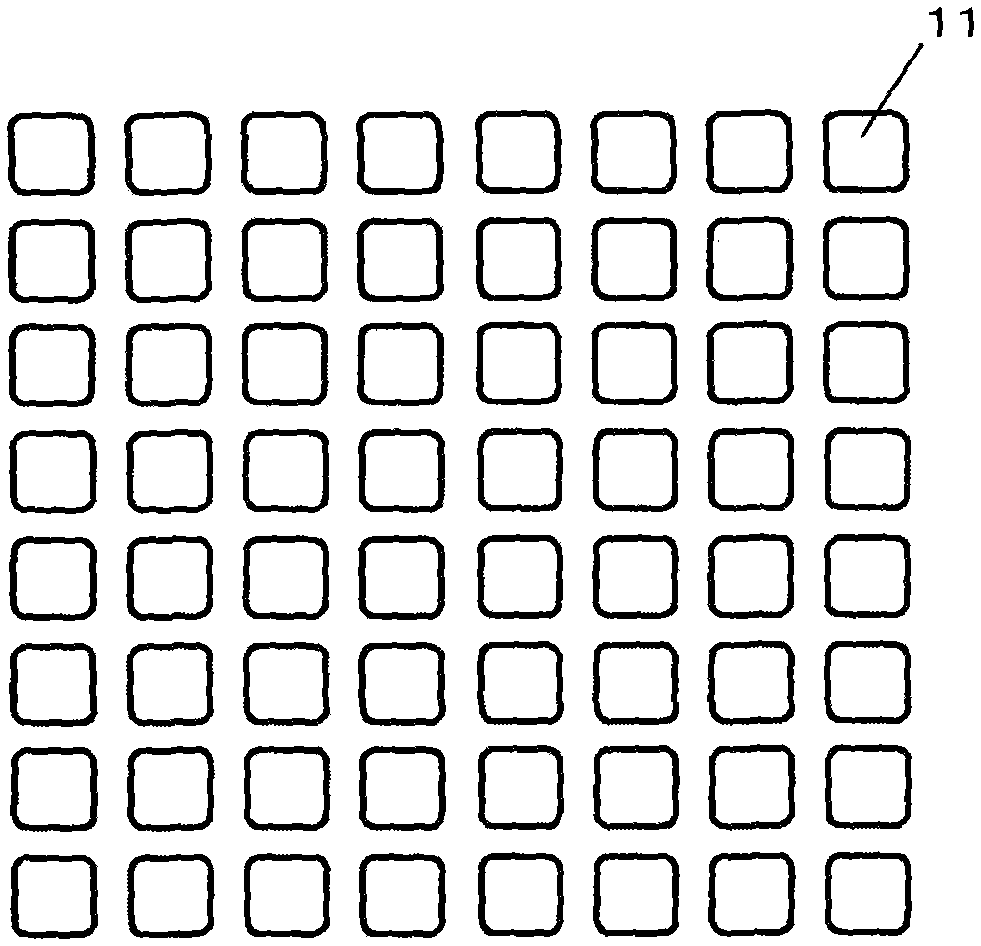
[0064] made as figure 2 Test panel with surface texture shown. Around the approximately 3 mm square concave portion 11, grid-shaped fine irregularities with a width of approximately 1.5 mm are provided. In addition, the concave portion 11 has a structure having the same height as the concave portion of the fine unevenness. That is, a structure positioned higher than the convex and concave portions of the fine unevenness. Adjust the fine unevenness so that when λc=0.08mm, Ra=0.822μm (Rz=3.665μm, Rt=10.938μm), when λc=0.8mm, Ra=7.644μm (Rz=33.724μm, Rt=51.104μm ).

[0065]Water was poured over the entire test panel using a shower to exhibit hydrophilicity, and the remaining water formed a thin water film. Regarding the drying performance, in method 1, all moisture is dried within about 4 hours. In Method 2, the hydrophilicity was not maintained due to the influence of the components of the conditioner, and the residual water formed water droplets, which did not dry for 4 h...

Embodiment approach 3

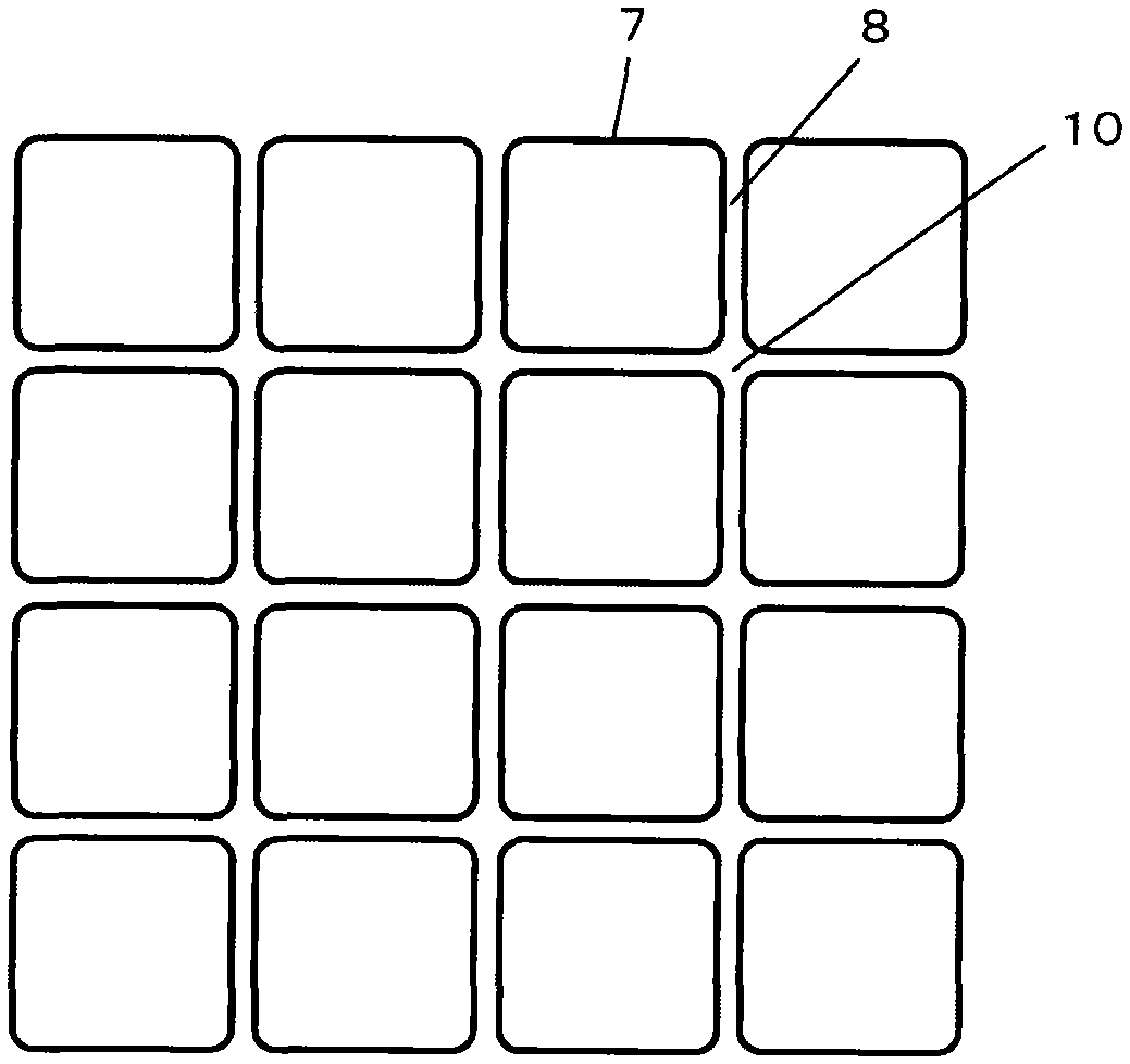
[0067] made as image 3 Test panel with surface texture shown. The convex part 7 is a square of about 12 mm, the depth of the groove part 8 is 0.4 mm, and the width is 0.4 mm. In addition, fine unevenness is implemented on the convex portion 7 and the groove portion 8, and the convex portion 7 is adjusted so that Ra=1.338 μm (Rz=6.411 μm, Rt=14.738 μm) when λc=0.08 mm, and Ra=1.338 μm when λc=0.8 mm. In mm, Ra=6.924 μm (Rz=35.389 μm, Rt=53.693 μm). Adjust the groove portion 8 so that Ra=1.411 μm (Rz=6.234 μm, Rt=14.163 μm) when λc=0.08 mm, Ra=4.886 μm (Rz=29.458 μm, Rt=39.017 μm) when λc=0.8 mm μm).

[0068] Water was poured over the entire test panel using a shower to exhibit hydrophilicity, and the remaining water formed a thin water film. Regarding the drying performance, in method 1, all moisture is dried within about 4 hours. In method 2, the hydrophilicity was not maintained due to the influence of the ingredients of the conditioner, but all the moisture was dried w...


PUM


Abstract

The invention aims to provide a bathroom floor forming part which is provided with a water drain hole and a bath region, wherein the bath region is provided with an inclined part for draining water from the end portion to the water drain hole; micro concavo-convex parts for preventing water gathering and avoiding water soaking spreading are formed on the surface of the bath region; and as the micro concavo-convex parts are appropriately regulated, the drying performance, the skid resistance, the easiness of dirt removal and the like of the floor forming part can be improved.

Description

technical field [0001] The present invention relates to a bathroom floor component suitable for use as a floor or a waterproof panel of bathroom units installed in apartments, general houses, and the like. Background technique [0002] In unit houses such as condominiums and general houses, bathrooms using floors made of waterproof FRP or the like are generally installed. Floors made of FRP, etc. are slippery and have low drying performance. Therefore, some floors have rock-like unevenness and joints for drainage that give the surface a non-slip effect. However, due to the surface tension of water droplets, A large amount of water will accumulate in the concave and convex parts and seams, making it difficult to dry. Therefore, by forming the flow path connected to the drain port or the drainage groove between the convex parts, and breaking the surface tension of the water droplets in the flow path, or implementing the flow velocity in the flow path The slow method prevents...

Claims


Application Information

Patent Timeline
Patent Type & Authority Patents(China)
IPC IPC(8): E04F15/00E03F5/00
Inventor 铃木弥志雄石灰宽彰楠原健太武市浩明内田贵之铃木明彦
Owner 株式会社好适特
Why Eureka
Try Eureka