Capacitive switching control method for inhibiting zero sequence and negative sequence current of distribution transformer
A technology of distribution transformer and negative sequence current, applied in the field of power system, can solve the problems of easy over-compensation and not considering the influence of distribution transformer governance effect.
- Summary
- Abstract
- Description
- Claims
- Application Information
AI Technical Summary
Problems solved by technology
Method used
Image
Examples
Embodiment 1
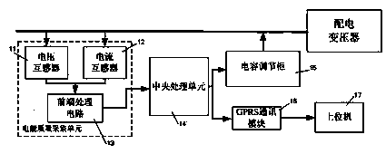
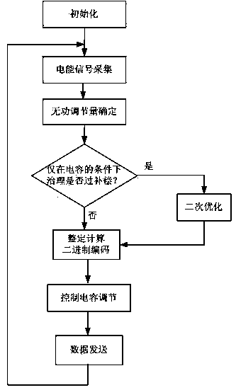
[0031] Example 1 as figure 1, a capacitive switching control system for suppressing zero-sequence and negative-sequence currents of distribution transformers, which consists of a voltage transformer 11, a current transformer 12, a front-end processing circuit 13, a central processing unit 14, a capacitor adjustment cabinet 15, and a GPRS communication The module 16 and the upper computer 17 are composed of the voltage transformer 11 and the current transformer 12 of the power quality acquisition unit to collect the voltage, current and neutral current signals of the transformer during operation, and transmit the collected signals to the central processing unit 14, the central processing unit 14 Calculate the voltage, current, and power factor according to the collected signals, and consider the harm of overcompensation to the distribution transformer, calculate the effective capacitance adjustment amount, obtain the control signal of the capacitance adjustment cabinet 15, and c...
Embodiment 2
[0032] Example 2, it is assumed that the three-phase voltage on the low-voltage side of the distribution transformer is = = =220V, the phase difference is 120 degrees, the three-phase current and power factor are respectively =11.9A, =23.2A, =10.3A, =0.92, =0.96, =0.73, the load is inductive, the reference capacity of the capacitor adjustment cabinet is 1kvar, and the adjustment range of phase-to-phase and phase-to-ground reactive power adjustment is 0kvar to 7kvar.
[0033] According to formula (1), the three-phase active power on the load side is obtained as follows:
[0034] =2.4kw, =4.9kw, =1.7kw;
[0035] According to formula (2), the inductive reactive power at the load side is obtained as:
[0036] =-1.0kvar, =-1.4kvar, =-1.5kvar;
[0037] At this time, the negative-sequence current is 5.1A, and the zero-sequence current is 3.7A. According to formula (3), calculate the reactive power adjustments that should be compensated between phases an...
PUM
 Abstract
Description
Claims
Application Information
 - R&D
- Intellectual Property
- Life Sciences
- Materials
- Tech Scout
- Unparalleled Data Quality
- Higher Quality Content
- 60% Fewer Hallucinations
Browse by: Latest US Patents, China's latest patents, Technical Efficacy Thesaurus, Application Domain, Technology Topic, Popular Technical Reports.
© 2025 PatSnap. All rights reserved.Legal|Privacy policy|Modern Slavery Act Transparency Statement|Sitemap|About US| Contact US: help@patsnap.com


