Ball mill connecting shaft device

A ball mill and connecting shaft technology, applied in grain processing and other directions, can solve the problems of reducing the service life of mechanical equipment, large motor impact, and large power grid impact, and achieve the effect of relieving equipment vibration, small power grid impact, and prolonging service life.

Inactive Publication Date: 2013-02-20
CHONGQING TIANZHIDAO SCI & TECH DEV
View PDF0 Cites 0 Cited by
  • Summary
  • Abstract
  • Description
  • Claims
  • Application Information

AI Technical Summary

Problems solved by technology

[0002] The ball mill cylinder and the driving motor of the current ball mill are matched and driven by a heavy-duty elastic pin coupling, which starts directly with a load, which has a large impact on the power grid and lasts for a long time. The starting current is 2.5 times the rated current of the motor. Larger, the starting power is 2.5 times the rated power, which reduces the service life of mechanical equipment

Method used


Image

  • Ball mill connecting shaft device

Examples


Embodiment Construction

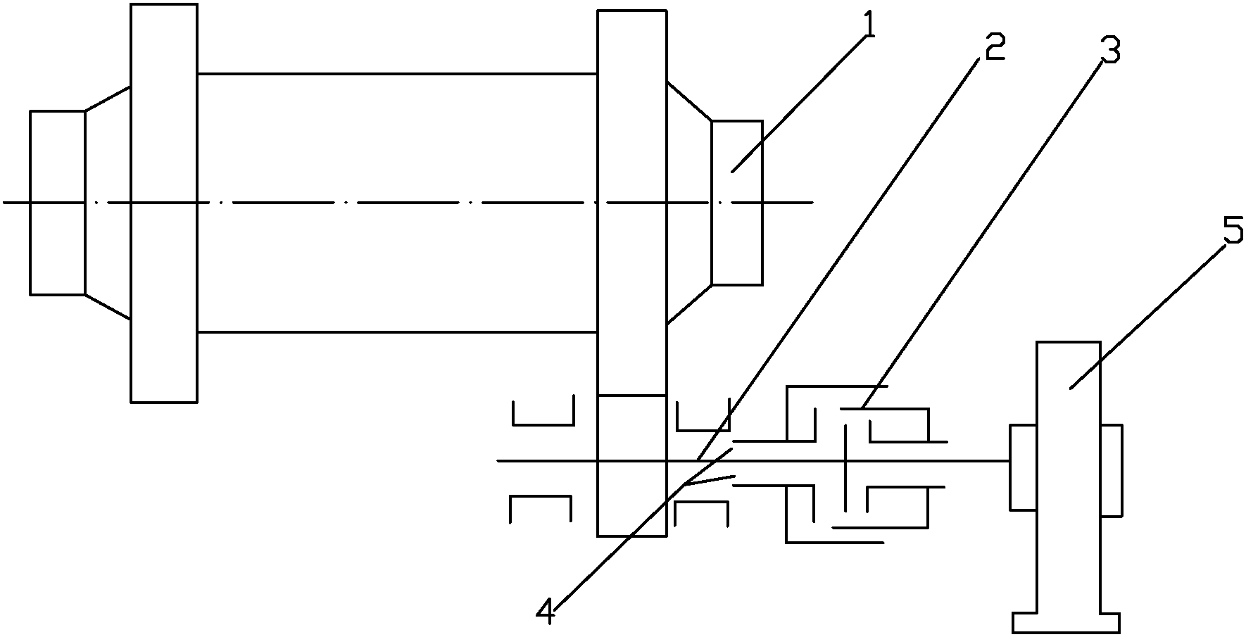
[0007] As shown in Figure 1, a ball mill coupling device of the present invention includes a ball mill 1, a drive shaft 2, an air clutch 3, and a synchronous motor 5, and the drive shaft 2 is connected with a ball mill 1, an air clutch 3, a synchronous motor 5, and the air pressure The clutch 3 is provided with an air pressure inlet and outlet 4, the transmission shaft 2 is connected to the gear of the ball mill 1, and the synchronous motor 5 is electrically controlled to drive the movement of the transmission shaft, but the air pressure clutch 3 drives the rotation of the transmission shaft 2 through the adjustment of the air pressure in the air pressure inlet and outlet , and finally the drive shaft 2 drives the ball mill to rotate through the meshing of the gears.

[0008] The above are only preferred embodiments of the present invention. It should be pointed out that for those skilled in the art, some modifications and improvements can be made without departing from the st...


PUM


Abstract

The invention discloses a ball mill connecting shaft device, relating to the technical field of ball mills. The ball mill connecting shaft device comprises a ball mill, a transmission shaft, an air pressure clutch and a synchronous motor, wherein the transmission shaft is sequentially connected with the ball mill, the air pressure clutch and the synchronous motor. By using the ball mill connecting shaft device, the defect of difficulty in starting caused by on-load starting and large rotational inertia of heavy mechanical equipment is overcome, and the service life of the ball mill connecting shaft device is prolonged.

Description

technical field [0001] The invention belongs to the technical field of ball mills, in particular to a ball mill coupling device. Background technique [0002] The ball mill cylinder and the driving motor of the current ball mill are matched and driven by a heavy-duty elastic pin coupling, which starts directly with a load, which has a large impact on the power grid and lasts for a long time. The starting current is 2.5 times the rated current of the motor. Larger, the starting power is 2.5 times the rated power, which reduces the service life of mechanical equipment. Contents of the invention [0003] The invention aims at the deficiencies of the prior art, and provides a ball mill coupling device with small current load, easy start-up and high service life. [0004] In order to solve the above-mentioned technical problems, the present invention provides the following technical solutions: The utility model is a new ball mill coupling device, which includes a ball mill, a ...

Claims


Application Information

Patent Timeline
IPC IPC(8): B02C17/24
Inventor 姜静慧
Owner CHONGQING TIANZHIDAO SCI & TECH DEV
Why Eureka
Try Eureka