Low-frequency-stage magnetic sensor background noise measuring method

A magnetic sensor and background noise technology, applied in the direction of noise figure or signal-to-noise ratio measurement, can solve the problems of poor accuracy of background noise, inability to accurately judge the performance of magnetic sensors, etc., and achieve the effect of accurate reflection

Active Publication Date: 2013-02-27
NO 722 RES INST OF CHINA SHIPBUILDING IND
View PDF6 Cites 19 Cited by
  • Summary
  • Abstract
  • Description
  • Claims
  • Application Information

AI Technical Summary

Problems solved by technology

However, the accuracy of the background noise of the magnetic sensor obtained through theoretical analysis is poor, generally smaller than the actual noise, and the performance of the magnetic sensor cannot be accurately judged.

Method used


Image

  • Low-frequency-stage magnetic sensor background noise measuring method
  • Low-frequency-stage magnetic sensor background noise measuring method
  • Low-frequency-stage magnetic sensor background noise measuring method

Examples


Embodiment

[0034] A method for measuring the background noise of a low-frequency band magnetic sensor, comprising the following steps:

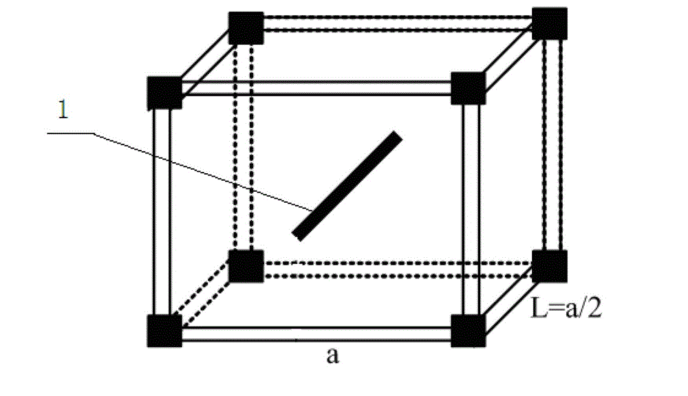
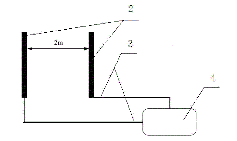
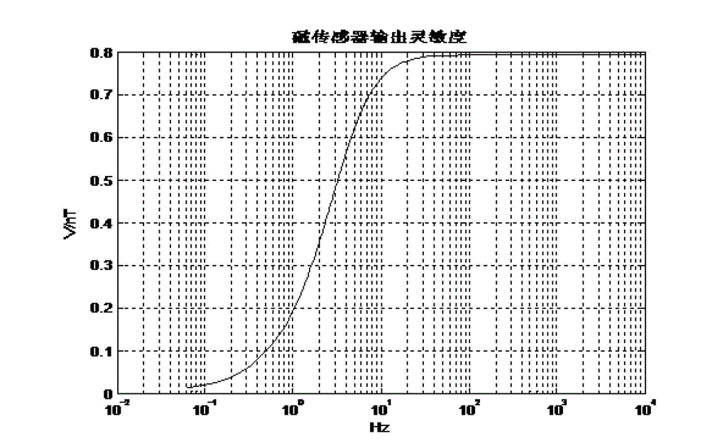
[0035] Consistency adjustment step: place the No. 1 magnetic sensor in the uniform magnetic field generating device, and sequentially input frequency sweep signals with fixed strength, different frequencies and the same phase to the uniform magnetic field generating device, and adjust the amplitude-frequency response curve of the magnetic sensor so that It is consistent with the design target curve; the No. 2 magnetic sensor is placed in the uniform magnetic field generating device, and the amplitude-frequency response of the magnetic sensor is adjusted by sequentially inputting frequency sweep signals with fixed strength, different frequencies and the same phase to the uniform magnetic field generating device Curve to make it consistent with the design target curve;

[0036] The noise floor differential measurement step: Place the No. 1 and No. 2 magne...


PUM


Abstract

The invention relates to a low-frequency-stage magnetic sensor background noise measuring method which is applicable to measuring the background noise of a low-frequency-stage magnetic sensor in a wild environment or a big shielding room. The method comprises the following steps that: response characteristics of amplitude frequencies and phase frequencies of two magnetic sensors are respectively adjusted to be accordant; the two sensors are horizontally arranged in parallel with a distance of 2-2.5m; two ends of the sensors are in parallel and level; the sensors sense identical natural horizontal field signals which belong to relevant signals; natural field signals can be eliminated by using a differentiation method; however, the background noise of the two sensors refers to an irrelevant random signal; and signal energy after the differentiation is the sum of noise energy of the two sensors. An average power spectrum of the signals after the differentiation is calculated, the average power spectrum is divided by 2 and is subjected to extraction of a root, and the background noise of a single sensor is calculated according to the output sensitivity of the magnetic sensors. The background noise of the low frequency stage magnetic sensor in a response bandwidth is accurately measured, and compared with a theoretical analysis method, the actual noise level of the magnetic sensor is relatively accurately reflected.

Description

technical field [0001] The invention relates to a method for measuring the noise of a magnetic sensor, in particular to a method for measuring the background noise of a low-frequency magnetic sensor, which is suitable for measuring the background noise of the low-frequency magnetic sensor in an outdoor environment or in a large shielded room. Background technique [0002] There are many kinds of noise in the amplification circuit, mainly three kinds, namely, thermal noise, 1 / f noise and shot noise. When designing a low-frequency magnetic sensor, the 1 / f noise is particularly obvious in the low-frequency amplifier, and the induction coil of the magnetic sensor, Magnetic cores etc. introduce noise. In order to ensure the performance of the low-frequency magnetic sensor, the noise floor of the sensor is required to be as low as possible, and its noise floor should be 20dB or more lower than the induced natural electromagnetic field signal. However, in the general natural envir...

Claims


Application Information

Patent Timeline
Patent Type & Authority Applications(China)
IPC IPC(8): G01R29/26
Inventor 张杨勇李文彬刘小林范育兵周志宇
Owner NO 722 RES INST OF CHINA SHIPBUILDING IND
Why Eureka
Try Eureka