Inflatable splint

A splint and inflatable ball technology, applied in the field of medical devices, can solve the problems of difficult dressing pressure, inconvenient pressure adjustment, troublesome dressing process, etc., and achieve the effects of easy fixing pressure, convenient fixing and convenient adjustment.

Inactive Publication Date: 2013-03-06
衣涛源
View PDF0 Cites 1 Cited by
  • Summary
  • Abstract
  • Description
  • Claims
  • Application Information

AI Technical Summary

Problems solved by technology

[0002] Splint is a commonly used tool in clinical surgery. When applying it, first press the splint on the injured part, fix it with bandaging tape, and then put plaster on it if necessary. Comfortable, inconvenient to adjust the pressure after fixing

Method used


Image

  • Inflatable splint
  • Inflatable splint

Examples


Embodiment Construction

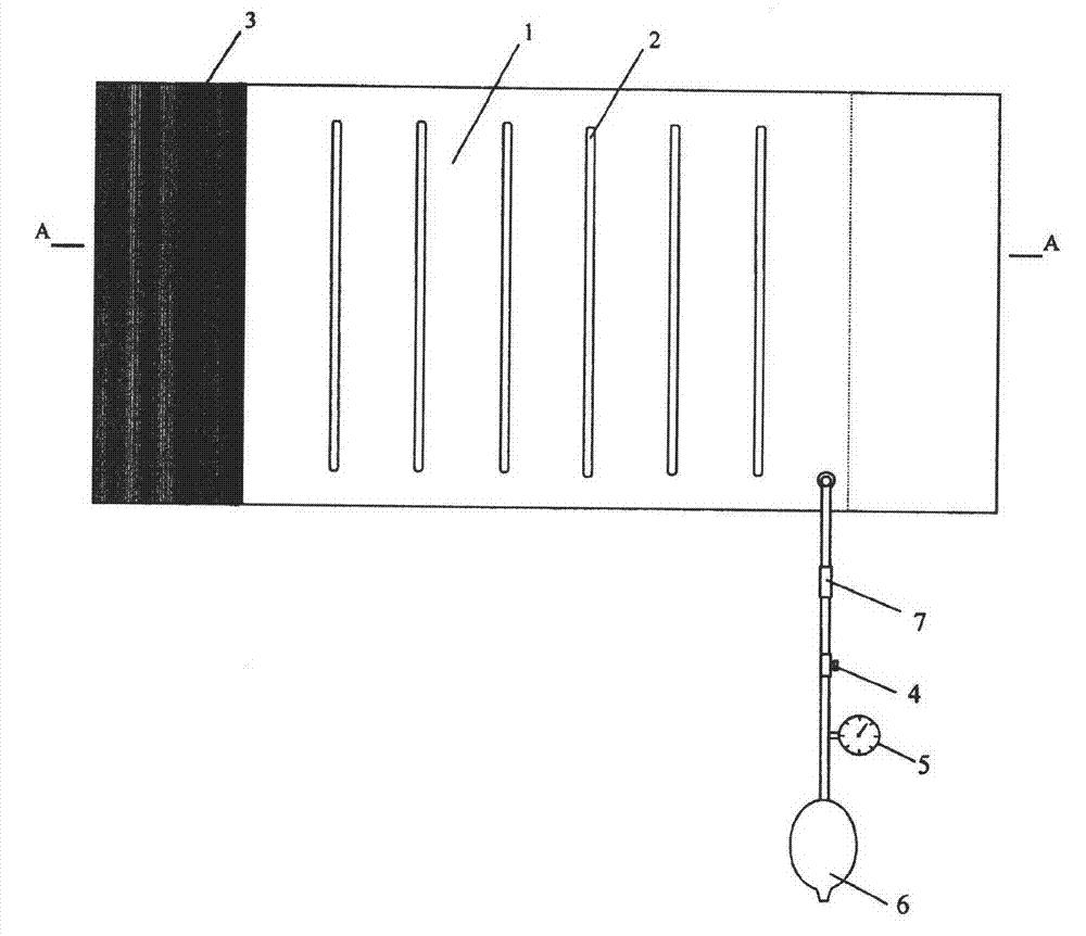
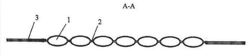
[0009] As shown in the figure, the inflatable belt is divided into a plurality of strip-shaped air chambers 1 by the airtight compression ribs 2. The upper and lower ends of the compression ribs 2 do not reach the edge of the inflatable belt. The upper and lower ends are connected to each other. The inflatable belt is connected to the air regulating valve 4, the barometer 5 and the inflatable ball 6 through the inflatable tube, and the movable joint 7 is arranged on the inflatable pipe, and the lower air regulating valve 4, the barometer 5 and the inflatable ball 6 can be connected with the inflatable pipe from the movable joint 7. unplug. The elastic adhesive tape 3 is connected to both sides of the inflatable belt.

[0010] The use method of the present invention is: wrap the inflatable belt on the injured part of the patient, use the adhesive tape 3 to bond and fix it, inflate inwardly through the inflatable ball 6, observe the barometer 5, stop when the required pressure ...


PUM


Abstract

The invention discloses an inflatable splint which comprises an inflating band connected with an air regulating valve, an air pressure meter and an inflating bladder. The inflating band consists of multiple strip-shaped air chambers combined together, press ribs which are closed are arranged in the middle of the strip-shaped air chambers, upper ends and the lower ends of the strip-shaped air chambers are communicated one another, and elastic adhesive tapes are connected to two sides of the inflating band. The inflatable splint is convenient to use and efficient and makes patients comfortable.

Description

technical field [0001] The invention relates to a surgical medical instrument, in particular to an inflatable splint, which belongs to the technical field of medical instruments. Background technique [0002] The splint is a commonly used tool in the clinical surgery. When applying it, the splint is first pressed on the injured part, fixed with a bandage, and then plastered if necessary. Comfortable and inconvenient to adjust the pressure when fixed. Contents of the invention [0003] The object of the present invention is to provide an inflatable splint that overcomes the above-mentioned shortcomings, is convenient to use, has high efficiency, and is comfortable for patients. [0004] The present invention is realized in the following way: an inflatable splint includes an inflatable belt connected to an air regulating valve, a barometer and an inflatable ball. Airtight compression ribs, the upper and lower ends of the strip-shaped air chambers are connected to each othe...

Claims


Application Information

Patent Timeline
IPC IPC(8): A61F5/058
Inventor 衣涛源
Owner 衣涛源
Why Eureka
Try Eureka