Sliding-rod sweep wing actuator

A technology for actuators and sliding arms, applied to switches with braking devices, wing parts, power control mechanisms, etc., can solve the problem of impossible detection of motor current

Inactive Publication Date: 2013-03-06
多玛德国有限公司
View PDF4 Cites 1 Cited by
  • Summary
  • Abstract
  • Description
  • Claims
  • Application Information

AI Technical Summary

Problems solved by technology

In general, it is not possible to detect the motor current

Method used


Image

  • Sliding-rod sweep wing actuator
  • Sliding-rod sweep wing actuator
  • Sliding-rod sweep wing actuator

Examples


Embodiment Construction

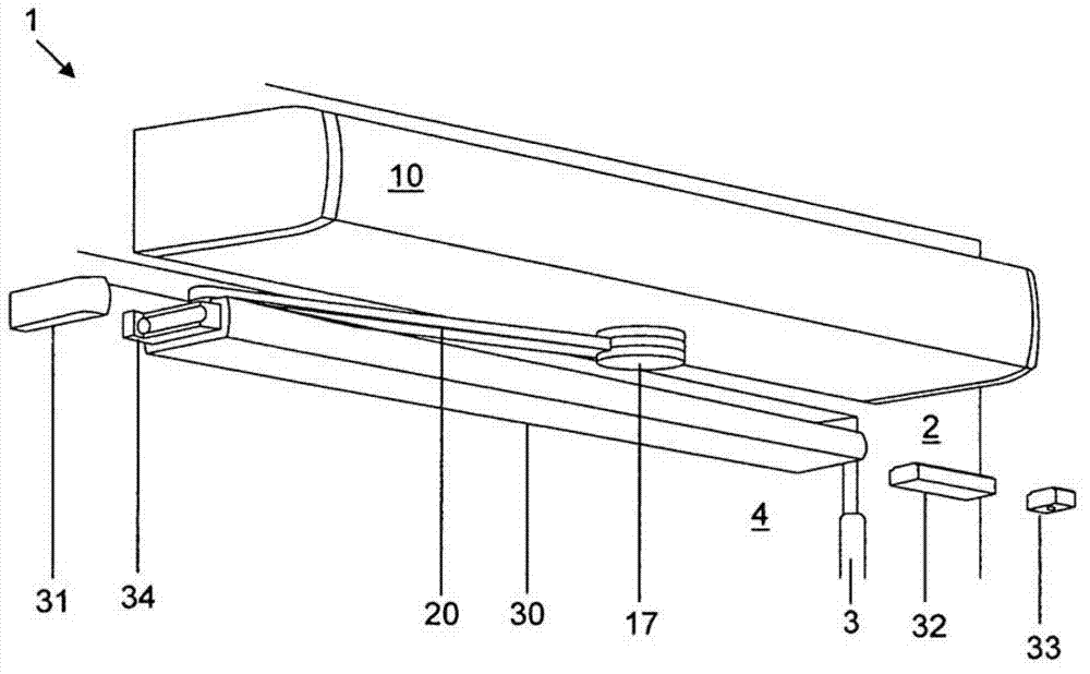
[0023] figure 1 An arrangement 1 is shown, which illustrates a swing-wing actuator 10 , which is configured, for example, as a door operator and is fixed overhead-mounted to a door frame as stationary carrier 2 . A swing wing 4 is fastened to the door frame 2 , wherein the swing wing 4 is likewise configured, for example, as a door leaf, so as to be pivotable via the door hinge 3 . The output shaft 11 of the door operator 10 , not visible in this case, is operatively connected via a sliding arm 20 to a slide rail 30 which is attached to the swing wing 4 in the usual manner. The attachment means of the slide arm 20 to the output shaft 11 is concealed by the cover 17 .

[0024] The slide rails 30 are preferably configured to be open towards both fronts and each terminate at the fronts by means of an end cap 31 , only the left end cap being shown in this case. Stopper 34 is inserted in the figure 1 Between the slide rail 30 in the center and the left end cap 31 , the stop 34 p...


PUM


Abstract

The invention relates to a sweep wing actuator (10) that has a slide rail (30) in which, in a manner already known, a sliding piece (22) of a sliding arm (20) of the sweep wing actuator (10) is translationally guided and held. Said sliding arm (20) is functionally connected to an output shaft (11) of the sweep wing actuator (10) such that, by means of the sliding piece (22) and the slide rail (30), said sweep wing actuator (10) is able to open and / or close a connected sweep wing (4). According to the invention, there is a sensor (35) in the slide rail (30) that is held in a locationally fixed manner such that said sensor (35) is able to detect the existence of at least one predetermined open state of the connected sweep wing (4).

Description

technical field [0001] The present invention relates to swing wing actuators based on sliding arm assemblies. Background technique [0002] A swing wing actuator suitable for opening and / or closing a connected swing wing is known, for example, from DE 10023760 A1. Such flap actuators are usually operatively connected to the door leaf to be pivoted by means of conventional arm assemblies or sliding arm assemblies. [0003] For hold-open devices, for example, it is important to know when the swing wing has reached the open position in which the hold-open device should be actuated. [0004] For oscillating-wing drives, the actuation is usually achieved by means of a summing encoder fixed to the rotating member of the oscillating-wing drive in a torque-bearing manner and by means of an existing power connection to the oscillating-wing drive or The data link is supplied with energy. [0005] Another option could be to monitor the current of the drive motor of the pendulum driv...

Claims


Application Information

Patent Timeline
Patent Type & Authority Applications(China)
IPC IPC(8): E05F15/12
CPCE05Y2201/11E05Y2600/40E05Y2400/324E05Y2400/322E05Y2400/354E05F5/12E05F15/127E05Y2400/65E05F2015/128E05Y2400/328E05Y2900/132E05F15/63E05F2015/631E05Y2600/45E05Y2600/46E05Y2800/17
Inventor 汉斯・约阿希姆・阿尔布雷希特
Owner 多玛德国有限公司
Why Eureka
Try Eureka