Target side distributor mechanism for connecting multiple functions to a single logical pipe of a computer interconnection bus

a distributor mechanism and computer interconnection technology, applied in the field of computer systems, can solve the problems of insufficient support for isochronous and asynchronous data on the major input/output bus of the present day computer system, and lack of system determinism,

Inactive Publication Date: 2002-09-24
ADVANCED MICRO DEVICES INC
View PDF20 Cites 17 Cited by
  • Summary
  • Abstract
  • Description
  • Claims
  • Application Information

AI Technical Summary

Problems solved by technology

The PCI bus causes a lack of determinism in the system because any function on the PCI bus can become master of the bus and tie up the bus.
PCI bus load fluctuations can result in uncertain and irregular quality of service.
Therefore, having a PCI bus as the major input / output bus means that the major input / output bus of present day computer systems does not provide proper support for both isochronous and asynchronous data.
If a computer system gives asynchronous data priority or treats isochronous data as asynchronous data, then those functions relying on real time data, such as motion-picture video, may not function satisfactorily.
Alternatively, if a computer system prioritizes isochronous data, then the performance of the computer system can suffer since the latency of asynchronous data may become unacceptably long.
Supporting the host bus, the memory interface, the PCI bus and a graphics interface results in a north bridge integrated circuit having a relatively large number of pins that is relatively unpopulated in terms of the number of transistors on the integrated circuit.
The large number of pins requires the integrated circuit to be larger than would otherwise be necessary and therefore increases costs.

Method used


Image

  • Target side distributor mechanism for connecting multiple functions to a single logical pipe of a computer interconnection bus
  • Target side distributor mechanism for connecting multiple functions to a single logical pipe of a computer interconnection bus
  • Target side distributor mechanism for connecting multiple functions to a single logical pipe of a computer interconnection bus

Examples


Embodiment Construction

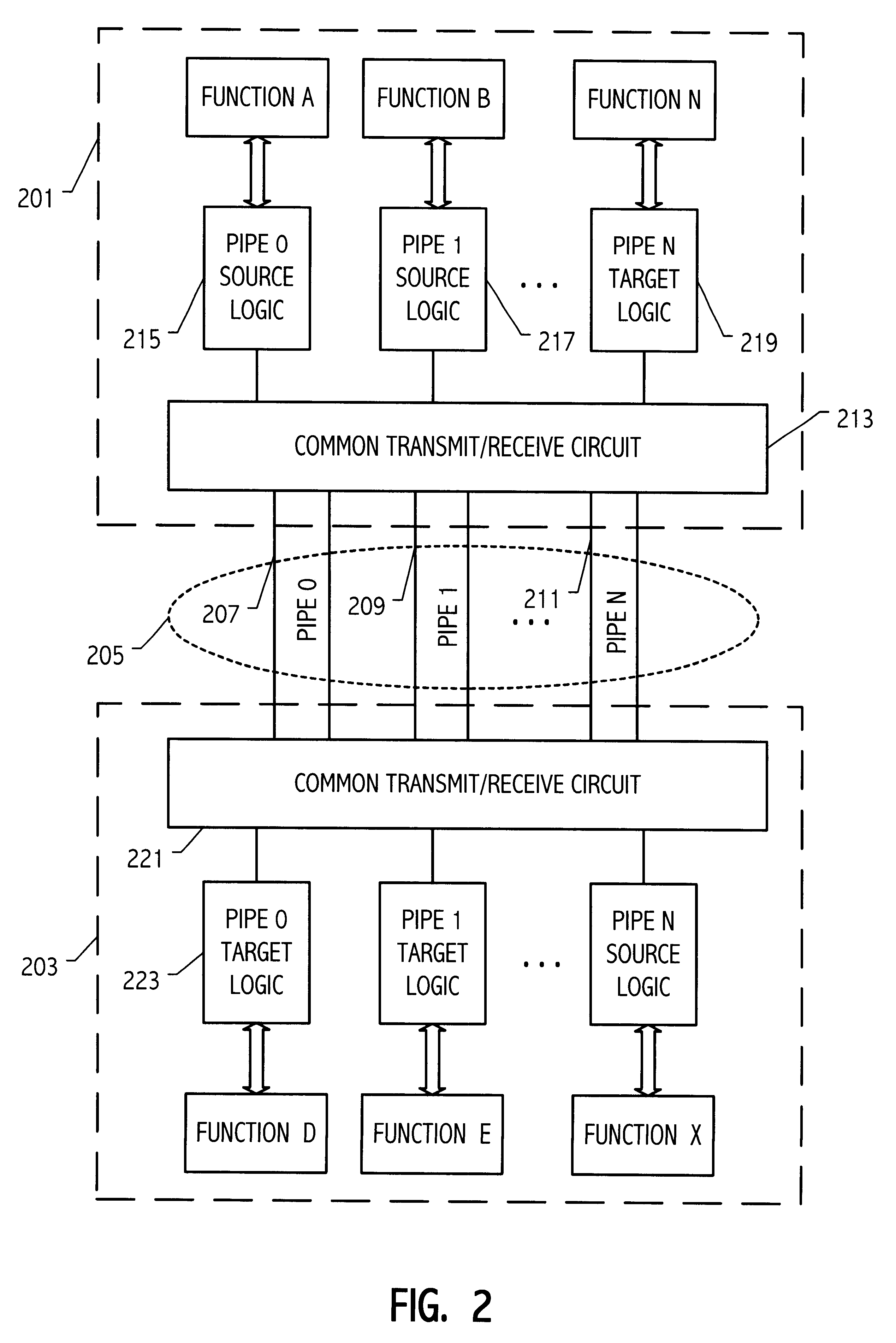
FIG. 2, illustrates a generic system according to one embodiment of the present invention. The system includes module 201 and module 203 coupled by high speed link 205. High speed link 205 is in one embodiment a low pin count high speed point to point bus (generally referred to herein as a "link" to distinguish the point to point interconnect bus from a multi-drop bus). The term "interconnect bus" is also used herein interchangeably with "link" to avoid confusion when discussing the "link layer" of the communication link. Examples of such a link are described in the following co-pending applications: application Ser. No.: 09 / 098,874, entitled BUS OPTIMIZED FOR PERSONAL COMPUTER TRAFFIC; application Ser. No. 09 / 099,227, filed Jun. 17, 1998, entitled METHOD OF MODE CONTROL IN A BUS OPTIMIZED FOR PERSONAL COMPUTER TRAFFIC; application Ser. No. 09 / 098,874, filed Jun. 17, 1998, entitled BUS OPTIMIZED FOR PERSONAL COMPUTER TRAFFIC; application Ser. No. 09 / 098,360 filed Jun. 17, 1998, enti...


PUM


Abstract

A computer system includes a first integrated circuit having a first function and a second integrated circuit having a plurality of second functions. A communication link connects the first integrated circuit and the second integrated circuit. The communication link includes at least one logical pipe having a source side on the first circuit and a target side on the second integrated circuit, the one pipe carrying transactions over the communication link between the first function and the second functions. The pipe is identified by a pipe identification carried in the transactions. A target side distributor circuit is coupled between the second functions and the communication link. The target side distributor circuit receives those transactions from the communication link having the pipe identification. The target side distributor circuit provides transactions received from the communication link having the pipe identification to respective ones of the second functions according to an address field included in the transactions.

Description

BACKGROUND OF THE INVENTION1. Field of the InventionThe invention relates to computer systems and more particularly to a computer system having a high speed communication link with multiple channels operating on the communication link.2. Description of the Related ArtTraditional personal computer architectures partition the computer system into the various blocks shown in the exemplary prior art system illustrated in FIG. 1. One central feature of this prior art architecture is the use of the Peripheral Component Interface (PCI) bus 101 as the connection between the "north bridge" integrated circuit 103 and the "south bridge" integrated circuit 105. The north bridge functions generally as a switch connecting CPU 107, a graphics bus 109 such as the Advanced Graphics Port (AGP) bus, the PCI bus and main memory 111. The north bridge also contains the memory controller function.The south bridge generally provides the interface to the input / output (I / O) portion of the system with the pos...

Claims


Application Information

Patent Timeline
Patent Type & Authority Patents(United States)
IPC IPC(8): G06F13/14H04L12/28
CPCG06F13/14H04L12/28G06F13/36
Inventor GULICK, DALE E.STRONGIN, GEOFFREY S. S.
Owner ADVANCED MICRO DEVICES INC
Why Eureka
Try Eureka