
Feeding mechanism for shafts and machine tool head adopting same

A feeding mechanism and shaft technology, applied in the field of feeding mechanism, can solve the problems of unadjustable feeding speed, complex structure, large volume, etc., and achieve the effect of good action continuity, compact overall structure and small installation volume.

Active Publication Date: 2013-03-13
NINGBO VISTART INTELLIGENT TECH
View PDF9 Cites 1 Cited by
  • Summary
  • Abstract
  • Description
  • Claims
  • Application Information

AI Technical Summary

Problems solved by technology

The traditional shaft feeding is mainly carried out by manual operation, which is time-consuming and labor-intensive, and the production efficiency is low
In order to effectively solve this problem, related feeding machines have been developed in the industry. Most of these machines have defects and deficiencies such as complex structure, poor feeding continuity, and unadjustable feeding speed.
[0003] The prior art discloses an improved feeder specifically for shafts, see the Chinese utility model patent "A Slender Shaft Feeder" with the patent number ZL201120362495.4 (the authorized announcement number is CN202296351U), the patent includes The upper part of the frame is equipped with a sloping plate for filling materials, and a slideway is vertically provided on one side of the frame. The lower side of the sloping plate for storing materials is provided with a feeding port, and the feeding port is connected with the slideway; the slideway can slide up and down. There is a slide plate, and there is a conveyor belt outside the side of the frame with a slideway. The conveyor belt is set in parallel with the slideway, and the energy is continuously fed to the shaft through the up and down movement of the slider, which greatly improves the production efficiency. This patent adopts the transmission To the transmission, the overall volume is large and the structure is relatively cumbersome, so it is not suitable for use on CNC shaft processing machine tools. Since the head space of the machine tool is relatively narrow, the above-mentioned disclosed feeder cannot be installed and installed. Therefore, it is necessary to develop a small and convenient Feeder installed and suitable for CNC shaft processing machine tools

Method used


Image

  • Feeding mechanism for shafts and machine tool head adopting same
  • Feeding mechanism for shafts and machine tool head adopting same
  • Feeding mechanism for shafts and machine tool head adopting same

Examples


Embodiment Construction

[0038] The present invention will be further described in detail below in conjunction with the accompanying drawings and embodiments.

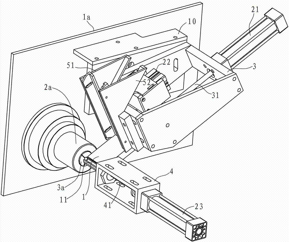
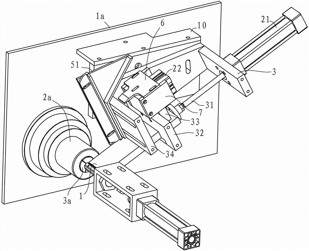
[0039] Such as figure 1 and figure 2 As shown, the machine tool head in this embodiment includes a machine tool baffle 1a, a machine tool spindle 2a, a connecting base plate 10, a support 3, a material box 5, a feeding plate 1, a first cylinder 21, a material shifting plate 6, and a second cylinder 22 , ejector rod and the third cylinder 23. The machine tool baffle 1a is vertically arranged, the machine tool spindle 2q is arranged horizontally on the machine tool baffle 1a, the machine tool spindle 2a is provided with a fixture 3a, the connection base plate 10 is arranged on the machine tool baffle plate 1a, and the bracket 3 and the connection base plate 10 are fixed as one.

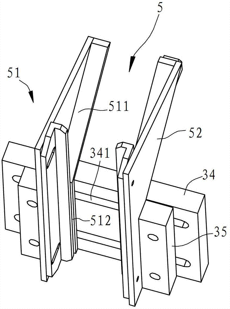
[0040] to combine image 3 and Figure 4 As shown, the material box 5 is located at the front end of the support 3, and the material box 5 includes a first materia...


PUM


Abstract

A feeding mechanism for shafts comprises a work bin, a feed plate, a first air cylinder, a material dialing plate, a second air cylinder, a material ejection plate and a third air cylinder, wherein the work bin is provided with a discharge port only allowing one workpiece to pass at a time; the feed plate is arranged below the work bin, used for undertaking the workpiece coming down the discharge port, and provided with a strip-shaped groove; the power output terminal of the first air cylinder is connected with the feed plate, and can drive the feed plate to move forth and back; the power output terminal of the second air cylinder is connected with the material dialing plate; the material ejection plate is arranged in parallel to the length direction of the strip-shaped groove; and the power output terminal of the third air cylinder is connected with the material ejection plate, and can drive the material dialing plate to move forth and back. Compared with the prior art, the feeding mechanism has the advantages that the operation continuity is excellent, the material leakage and malposition rates are small, the over-all structure is simple and compact, and the installation volume is small; and the feeding mechanism is suitable for being arranged on a numerical control processing machine tool for the shafts.

Description

technical field [0001] The invention relates to a feeding mechanism, in particular to a shaft feeding mechanism, which can be applied to the machine head of a numerically controlled machine tool. The invention also discloses a machine head using the feeding mechanism. Background technique [0002] Production and processing of shafts is common in various mechanical manufacturing fields. The production process of shaft processing generally includes two processes of feeding and processing, in which the feeding process directly determines the level of production efficiency. The traditional shaft feeding is mainly carried out by manual operation, which is time-consuming and labor-intensive, and the production efficiency is low. In order to effectively solve this problem, related feeding machines have been developed in the industry. Most of these machines have defects and deficiencies such as complex structure, poor feeding continuity, and unadjustable feeding speed. [0003] T...

Claims


Application Information

Patent Timeline
Patent Type & Authority Applications(China)
IPC IPC(8): B23Q7/00
Inventor 贝国生
Owner NINGBO VISTART INTELLIGENT TECH
Learn More