High-pressure gas detector

A high-pressure, compressed cylinder technology, applied in the testing of machine/structural components, through the measurement of the increase and deceleration rate of the fluid, the measurement device, etc., can solve the problems of difficult control of force, heavy weight of the frame, and complicated operation process, etc., to achieve The detection process is smooth and efficient, the overall structure is reasonable, and the effect of strengthening the sealing effect

Active Publication Date: 2016-08-03
玫德雅昌(德庆)管业有限公司
View PDF12 Cites 0 Cited by
  • Summary
  • Abstract
  • Description
  • Claims
  • Application Information

AI Technical Summary

Problems solved by technology

[0004] The above-mentioned test method has the following disadvantages: 1. The operation process is complicated, and the weight of the frame is relatively heavy. It is necessary to immerse the frame in water with the help of external equipment, and the installation of the steel-plastic conversion joint is also relatively troublesome; When the steel-plastic conversion joint is sealed and the sealing ring is placed outside the two ends of the steel-plastic conversion joint, and the hydraulic cylinder (or air cylinder) is used to clamp the two ends of the steel-plastic conversion joint for sealing, the strength of both is difficult to control. If the pressing or clamping force is not enough, the seal at the end of the steel-plastic conversion joint may not be reliable, which will affect the accuracy of the test and cause misjudgment of quality. If the pressing or clamping force is excessive, it may cause The deformation of the steel-plastic conversion joint causes the end face (pipe end) of the steel-plastic conversion joint to be uneven, which makes it impossible to form a seal between the steel-plastic conversion joint and the pressure plate, resulting in misjudgment of quality. Excessive force may also directly damage the steel-plastic conversion joint

Method used


Image

  • High-pressure gas detector
  • High-pressure gas detector
  • High-pressure gas detector

Examples


Embodiment Construction

[0025] The present invention will be further described below in conjunction with the accompanying drawings and specific embodiments.

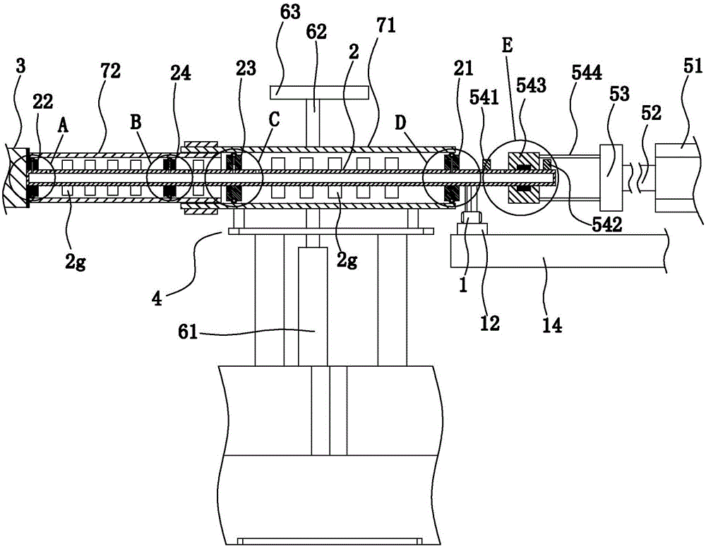
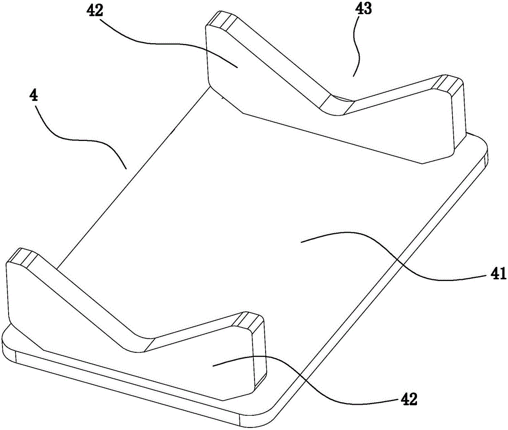
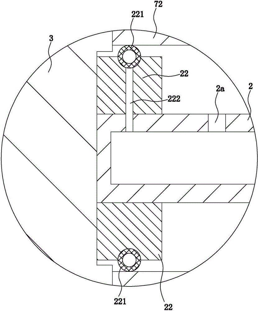
[0026] Such as Figure 1 to Figure 7 In the shown embodiment, a high-pressure gas detection machine includes a main base, an air supply pump 1, a plugging cylinder, a compression cylinder, a limit seat 3, a horizontal shaft tube 2 with both ends closed, and a For the joint support frame 4 that supports the steel-plastic conversion joint and makes the axis of the steel-plastic conversion joint in a horizontal state, the plugging cylinder, the compression cylinder, and the joint support frame are all arranged on the main base, and the sealing cylinder includes a head cylinder Body 51, the head cylinder piston that is sliding and sealingly matched with the head cylinder body, the head piston rod 52 connected with the head cylinder piston, the head piston rod is horizontal and the retractable direction of the head piston rod is horizontal, and the ...


PUM


Abstract

The present invention discloses a high-pressure gas detector. The high-pressure gas detector comprises a host base, an air feed pump, a blocking cylinder, a compaction cylinder, an axle tube, a spacing base and a joint bracing frame. The compaction piston rod is provided with a location board, and an end socket piston rod is provided with a driving rack; the axle tube is provided with a plastic pipe outer end blanking plate, a steel pipe outer end blanking plate, a plastic pipe external seal ring and a steel pipe external seal ring; the axle tube is provided with a first air intake, and the first air intake is provided with a first air intake non-return valve; the outer wall of the axle tube is provided with a first air pressure sensor, the steel-plastic conversion connector supported by the joint bracing frame is located between the spacing base and the blocking cylinder, and the air supply pipe of the air feed pump internally communicates with the axle tube through the air supply pipe. The high-pressure gas detector is reasonable in integration structure, is able to locate and clamp the steel-plastic conversion connector in place and guarantee the sealing without damaging the steel-plastic conversion connector, and has a sealing structure with adaptive regulation so as to reinforce the sealing effect at high-pressure detection.

Description

technical field [0001] The invention belongs to the technical field of tightness testing of pipe joints, and in particular relates to a high-pressure gas detection machine. Background technique [0002] Steel-plastic conversion joints, also known as PE steel-plastic conversion joints, have been widely used in current production and life. For example, steel-plastic conversion joints are widely used in gas and natural gas transportation pipelines (most of the external gas pipelines are PE Pipes are mostly steel pipes when entering the room, and steel-plastic conversion joints are required during the transfer process). The steel-plastic conversion joint itself consists of a steel pipe section (a section of steel pipe) and a plastic pipe section (usually a section of PE pipe). One end of the steel pipe section is docked with one end of the plastic pipe section to form a connection section. The connection section is usually clamped by one end of the steel pipe section and one end...

Claims


Application Information

Patent Timeline
Patent Type & Authority Applications(China)
IPC IPC(8): G01M3/28
CPCG01M3/2853
Inventor 宣月罗
Owner 玫德雅昌(德庆)管业有限公司
Why Eureka
Try Eureka