Brake control device for railway carriages

A technology of brake control and railway passenger cars, which is applied in the direction of railway car body parts, pneumatic brakes, hydrostatic brakes, etc., can solve the problems of stability gap, failure to be loaded and used, shorten idling time, etc., and achieve easy interlocking The effect of control

Active Publication Date: 2013-03-13
NANJING CRRC PUZHEN HAITAI BRAKE EQUIP CO LTD
View PDF6 Cites 35 Cited by
  • Summary
  • Abstract
  • Description
  • Claims
  • Application Information

AI Technical Summary

Problems solved by technology

Although the two electric control motors have greatly improved the braking wave speed transmission, shortened the idling time, and improved the impact to a certain extent; but due to the unique operation mode of the railway passenger car and the stability of the valve, there are still some problems. gap, it has not been widely loaded and used in various road bureaus

Method used


Image

  • Brake control device for railway carriages

Examples


Embodiment Construction

[0015] In order to make the purpose, technical solutions and advantages of the embodiments of the present invention clearer, the technical solutions in the embodiments of the present invention will be clearly and completely described below in conjunction with the drawings in the embodiments of the present invention. Obviously, the described embodiments It is a part of embodiments of the present invention, but not all embodiments. Based on the embodiments of the present invention, all other embodiments obtained by persons of ordinary skill in the art without creative efforts fall within the protection scope of the present invention. It should be noted that the drawings are all in very simplified form and use imprecise ratios, which are only used to facilitate and clearly assist the purpose of illustrating the embodiments of the present invention.

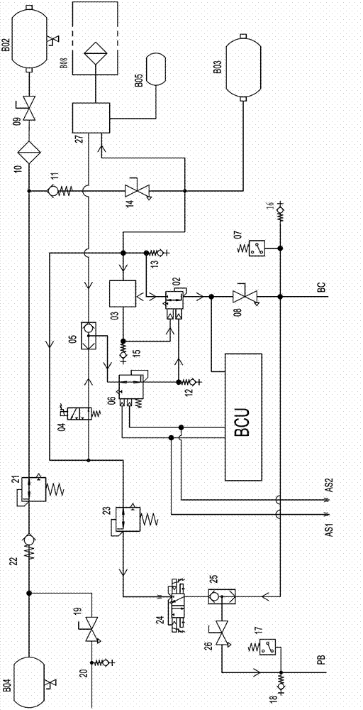
[0016] The present embodiment railway passenger car brake control device, such as figure 1 As shown, the composition includes: bra...


PUM


Abstract

The invention provides a brake control device for railway carriages. The brake control device comprises a brake air cylinder, a brake controller, an electric pneumatic change-over valve, a relay valve, an emergency electromagnetic valve, a load adjustment valve, a brake two-way valve, a distribution valve and a working air cylinder, wherein the brake controller outputs a current signal for to the electric pneumatic change-over valve; the electric pneumatic change-over valve converts the current signal into a pilot control pressure signal and then sends to a first pressure input port of the relay valve; the relay valve performs flow amplification on the pilot control pressure signal and inputs a brake cylinder pipe; two pressure input ports of the brake two-way valve are respectively connected with pressure output ports of the emergency electromagnetic valve and the distribution valve through pipelines; the pressure input port of the brake two-way valve is connected with a second pressure input port of the relay valve through the load adjustment valve; and an adjustment signal input port of the load adjustment valve is communicated with two air springs. According to the brake control device, a microcomputer controlled direct electric pneumatic brake system and an air automatic brake system are integrated. Under normal conditions, the direct system is used; and the automatic system is taken as a safe brake method to satisfy rescue and loopback requirements.

Description

technical field [0001] The invention relates to a braking control device for railway passenger cars, which is used for braking the fixed-group railway passenger cars and belongs to the technical field of railway passenger car braking systems. Background technique [0002] On the braking system of domestic railway passenger cars, the traditional air brake is generally used at present. The working principle of the traditional air brake is to produce the braking effect according to the decompression of the train tube. Different decompression amounts form different levels of braking force. Due to the relatively slow transmission speed of air pressure waves, in the case of long formations, the train often has a certain longitudinal impulse due to the delay in command transmission, which affects the comfort of passengers. Domestic brake manufacturers have also improved the design of traditional air brakes and developed electric control motors. Although the two electric control ...

Claims


Application Information

Patent Timeline
Patent Type & Authority Applications(China)
IPC IPC(8): B61H11/06
Inventor 吴明赵朱新宇韩继生汪枫
Owner NANJING CRRC PUZHEN HAITAI BRAKE EQUIP CO LTD
Why Eureka
Try Eureka