
Multi-field infrared optical system and its radial insertion multi-field switching device

An infrared optical system and field of view switching technology, applied in optics, optical components, installation, etc., can solve the problems of lens group offset optical axis position, system impact, loss of tracking target, etc., to achieve accurate target tracking, reduce impact, The effect of improving the reliability of use

Inactive Publication Date: 2016-04-20
LUOYANG INST OF ELECTRO OPTICAL EQUIP OF AVIC
View PDF3 Cites 0 Cited by
  • Summary
  • Abstract
  • Description
  • Claims
  • Application Information

AI Technical Summary

Problems solved by technology

The defect of this multi-field-of-view switching infrared imaging system is that when the corresponding lens group needs to be moved in or out, when the sensor detects that the lens group is in place, the control device controls the high-speed rotating zoom motor to stop quickly. , but when the zoom motor stops, the high-speed motion of the lens group will have a large impact on the system due to the action of inertial force, which will cause the lens group to shift the position of the optical axis, making the infrared imaging system easy to lose track of the target when switching the field of view

Method used


Image

  • Multi-field infrared optical system and its radial insertion multi-field switching device
  • Multi-field infrared optical system and its radial insertion multi-field switching device
  • Multi-field infrared optical system and its radial insertion multi-field switching device

Examples


Embodiment Construction

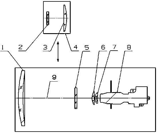
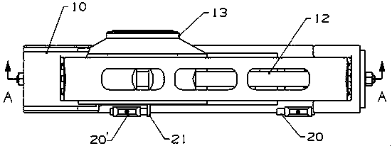
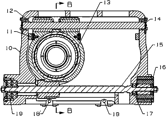
[0019] Specific embodiments of the multi-field infrared optical system of the present invention are as follows: Figure 1 to Figure 4 As shown, it is sequentially provided with a large objective lens 1, a focusing lens unit 5, a first converging lens 6, a second converging lens 7 and an image receiving unit 8 along the optical axis 9, and is located in the large optical path in front of the focusing lens unit 5. Between the objective lens 1 and the focusing lens unit 5 is provided a radially inserted multi-view field switching device 4 for moving in and out radially in a direction perpendicular to the optical axis to switch between different fields of view. The radial insertion type multi-field switching device 4 includes a mounting bracket 10, in which the field of view switching device that moves in or out of the corresponding optical axis position under the drive of a motor is guided and installed by a linear guide mechanism extending in a direction perpendicular to the opti...


PUM


Abstract

The invention discloses a multi-field infrared optical system, which is provided with a radially inserted multi-field switching device for switching different fields of view on the optical path in front of the focusing lens unit. The radially inserted multi-field The switching device includes a field of view switching lens unit that moves in or out of the corresponding optical axis position in the radial direction, and is respectively provided with a moving-in sensor and a Move out sensor and move in deceleration sensor and out deceleration sensor. The multi-field infrared optical system of the present invention controls the motor to decelerate through the corresponding deceleration sensor when switching the field of view, thereby reducing the impact on the system when the field of view switching lens unit moves in place, and avoiding the lens group during the field of view switching process The position of the optical axis is shifted to ensure that the infrared imaging system can accurately track the target when the field of view is switched, and the reliability of the infrared imaging system is improved.

Description

technical field [0001] The invention relates to a multi-field infrared optical system and a radially inserted multi-field switching device for switching different fields of view in the optical system. Background technique [0002] The switching of each field of view in the existing multi-field infrared optical system mainly adopts the axial variable magnification switching method, which changes the distance between the lenses by moving the lens group along the optical axis and then changes the focal length of the system to switch between different fields of view. The number of lenses involved in infrared optical imaging in this axial zoom switching mode is large, which reduces the transmittance of the infrared optical system, reduces the transmittance, increases the system aberration, and causes the imaging quality of each field of view to vary. is affected, which reduces the detection distance and resolution of the infrared photoelectric detection system. Chinese Invention...

Claims


Application Information

Patent Timeline
Patent Type & Authority Patents(China)
IPC IPC(8): G02B27/00G02B7/04
Inventor 张久锋李运动
Owner LUOYANG INST OF ELECTRO OPTICAL EQUIP OF AVIC
Learn More