Conversion device

A technology for switching devices and switching components, which is applied in the direction of coupling devices, components of connecting devices, electrical components, etc., and can solve problems such as waste of resources

Active Publication Date: 2013-03-13
XIAOMI INC
View PDF4 Cites 10 Cited by
  • Summary
  • Abstract
  • Description
  • Claims
  • Application Information

AI Technical Summary

Problems solved by technology

[0007] The embodiment of the present invention provides a conversion device to solve the problem that there are multiple standards and plug types for earphone plugs, and most devices can only support earphone plugs of one

Method used


Image

  • Conversion device
  • Conversion device
  • Conversion device

Examples


Embodiment 1

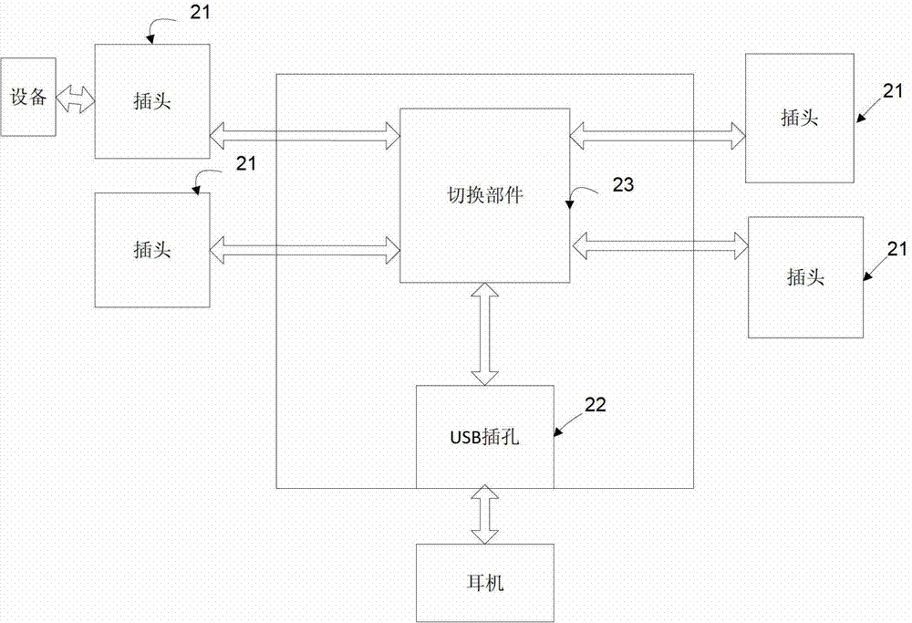
[0040] like figure 2 As shown, the conversion device provided by the embodiment of the present invention includes at least one plug 21, a USB jack 22 and a switching component 23;

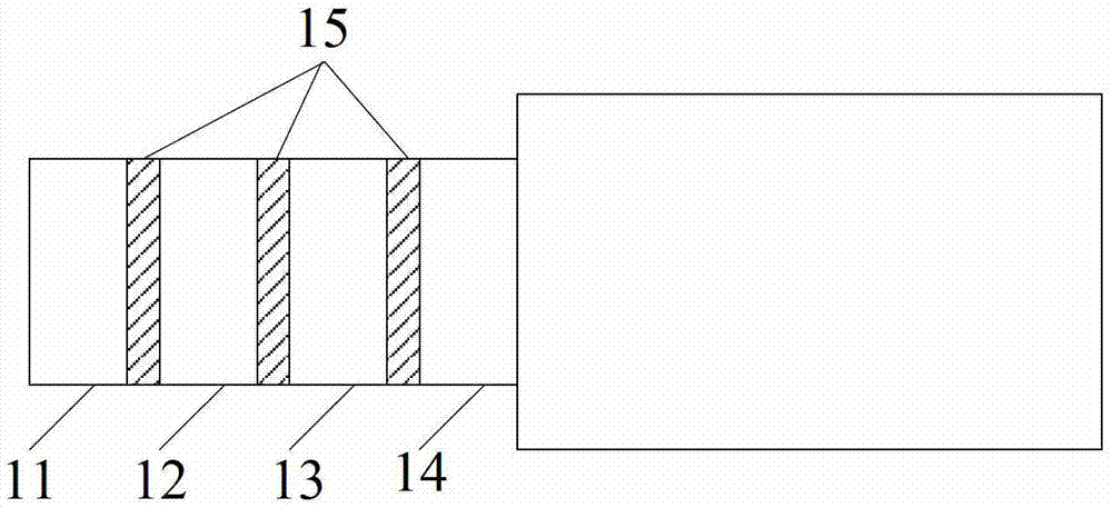
[0041] In this embodiment, the plug 21 includes: a first pin, a second pin, a third pin, and a fourth pin, wherein the first pin is used to receive the left audio output from the device connected to the conversion device. channel signal, the second pin is used to receive the right channel signal output by the device, and the third pin is used to receive the signal input by the microphone and sent to the device or to receive the ground signal output by the device , the fourth pin is used to receive a ground signal output by the device or to receive a signal input by a microphone and sent to the device;

[0042]In this embodiment, the USB jack 22 includes: a first data terminal, a second data terminal, a user identification pin (Identity pin, ID) and a ground pin (Ground pin, GND), wherein the firs...

Embodiment 2

[0064] The embodiment of the present invention also provides a conversion device, such as Figure 11 As shown, it includes: a jack 31, a connecting part 32, a USB plug 33 and a switching part 34;

[0065] The connecting part 32 includes: a first pin, a second pin, a third pin and a fourth pin, wherein the first pin is used to receive the left channel signal output by the equipment connected to the conversion device , the second pin is used to receive the right channel signal output by the device, the third pin is used to receive the signal input by the microphone and sent to the device, and the fourth pin is used to receiving a ground signal output by the device;

[0066] The USB plug 33 includes: a first data terminal, a second data terminal, a user identification pin and a ground pin, wherein the first data terminal is connected to the first pin, and the second data terminal is connected to the ground pin. The second pin is connected, the user identification pin is connect...


PUM

PropertyMeasurementUnit
Diameteraaaaaaaaaa
Internal diameteraaaaaaaaaa

Abstract

The embodiment of the invention provides a conversion device, which comprises at least one plug, an USB jack and a conversion component, wherein a first pin of the plug is used for receiving a left sound channel signal; a second pin of the plug is used for receiving a right sound channel signal; a third pin of the plug is used for receiving a signal input by a pair of microphones or a ground signal output by equipment; a fourth pin of the plug is used for receiving the ground signal output by the equipment or the signal input by the microphones; the conversion component controls a first data terminal of an USB interface to be connected with the first pin, a second data terminal of the USB interface to be connected with the second pin, a user identification(UID) pin to be connected with the third pin for receiving the signal input by the microphones and transmitted to the equipment and a ground wire pin to be connected with the fourth pin for receiving the ground signal output by the equipment; or the conversion component controls the UID pin to be connected with the third pin for receiving the ground signal output by the equipment and the ground wire pin to be connected with the fourth pin for receiving the signal input by the microphones and transmitted to the equipment.

Description

technical field [0001] The invention relates to the field of electronic devices, in particular to a conversion device. Background technique [0002] At present, earphone plugs are mainly divided into two standards, one is the open mobile terminal platform standard, that is, the national standard, and the other is the mobile communication industry association standard, that is, the American standard. These two standards differ in the arrangement of the pins. . Figure 1a It is a schematic diagram of the structure of the American standard headphone plug. Pin 11 is used to output the left channel signal, pin 12 is used to output the right channel signal, pin 13 is used for grounding, and pin 14 is used to receive the signal input by the microphone. Figure 1b It is a schematic diagram of the structure of the national standard earphone plug. It also outputs the left channel signal from pin 11, the right channel signal from pin 12, grounds the pin 13, and receives the signal inpu...

Claims


Application Information

Patent Timeline
IPC IPC(8): H01R31/06H01R13/66H01R13/70
Inventor 熊鑫许春利石新明
Owner XIAOMI INC
Why Eureka
Try Eureka