Service flow transmission path optimizing method and device and MME

A path optimization and stream transmission technology, applied in the field of communication, can solve the problem of waste of transmission path resources, etc.

Active Publication Date: 2016-07-27
ZTE CORP
View PDF4 Cites 7 Cited by
  • Summary
  • Abstract
  • Description
  • Claims
  • Application Information

AI Technical Summary

Problems solved by technology

[0054] The present invention provides a service flow transmission path optimization method, device and M

Method used


Image

  • Service flow transmission path optimizing method and device and MME
  • Service flow transmission path optimizing method and device and MME
  • Service flow transmission path optimizing method and device and MME

Examples


Embodiment 1

[0106] This embodiment describes the TAU switching process of the user, that is, when the user moves, the user's latest TA (Tracking Area) is not in the user's TAI (Tracking Area Identity) list, and cross-MME switching needs to occur. A new MME needs to be selected for the user to serve the user access. In this embodiment, it is assumed that the user is carrying out real-time services and non-real-time services before handover. During the handover process, the target MME (new MME) can obtain the user's CSIPTO indication information from the source MME.

[0107] The UE can subscribe to multiple APNs, and the user terminal can use each APN to establish one PDN connection or multiple PDN connections. The following process messages are for the PDN connection level. If the UE uses multiple APNs to establish multiple PDN connections before handover, or uses a single APN to establish multiple APN connections, each PDN connection has a corresponding message flow. For the convenience o...

Embodiment 2

[0133] This embodiment describes the TAU switching process of the user, that is, when the user moves, the user's latest TA is not in the user's TAI list, and cross-MME switching needs to occur, and a new MME needs to be selected for the user to serve the user. In this embodiment, it is assumed that the user is carrying out real-time services and non-real-time services before handover. During the handover process, the target MME (new MME) obtains the user's CSIPTO indication information from the HSS.

[0134] Picture 11 Is a flowchart according to the second embodiment of the present invention, such as Picture 11 As shown, the process includes the following steps:

[0135] 1. The system detects that the UE has moved, and its latest TA is not in the TAI list, and triggers the TAU procedure.

[0136] 2. The UE initiates a TAU request message to the eNodeB. The message carries RRC parameters.

[0137] 3. The eNodeB selects a new MME (ie target MME) according to the RRC parameters. Th...

Embodiment 3

[0160] In the S1 handover scenario described in the third embodiment, during the S1 handover process, a cross-MME handover also needs to occur.

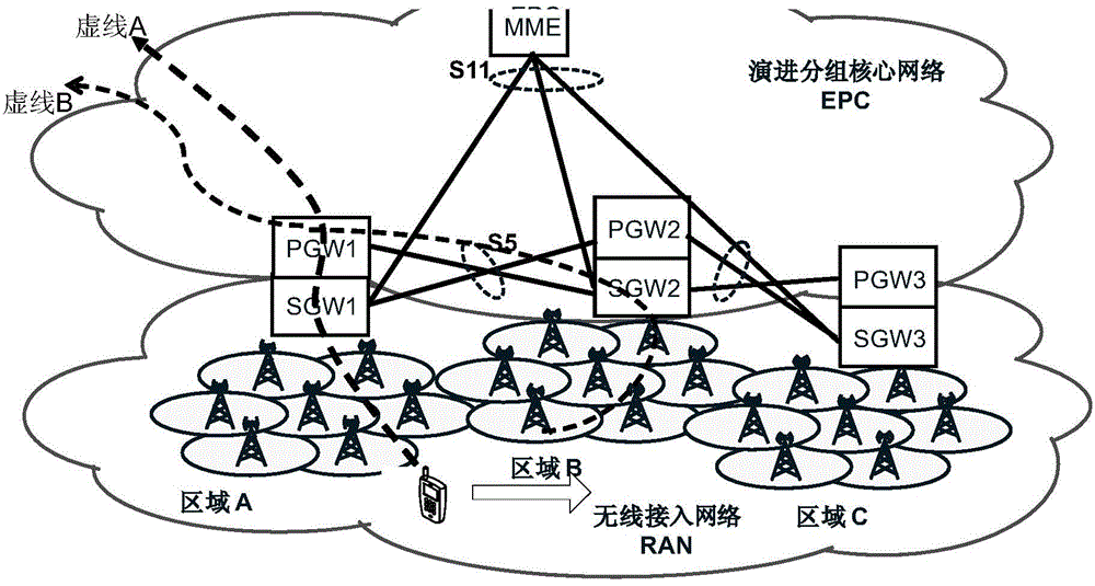
[0161] Before the handover, the service carried out by the UE uses the PDN connection established between the UE, the source eNodeB, the source S-GW and the P-GW1 for data routing. The services carried out by the UE include real-time services and non-real-time services.

[0162] After that, an S1 handover occurs in the UE, that is, a cross-MME handover needs to occur.

[0163] Picture 12 Is a flowchart according to the third embodiment of the present invention, such as Picture 12 As shown, the process includes the following steps:

[0164] Steps 1-17 describe that in the S1 handover process, the service data is forwarded from the source access network to the target access network after the handover by establishing an indirect data forwarding channel mechanism. The process refers to the prior art process.

[0165] As described in step 18,...


PUM


Abstract

The invention discloses a service flow transmission path optimizing method and device and an MME. The method comprises the steps that in the switching process of user equipment UE, when mobile management entity MME switching is carried out, CSIPTO instruction information, which carries out grouped data gateway P-GW adjustment on specified internet protocol IP flow unloading, of the UE is acquired from a source MME which switches a former service for the UE or a home subscriber server HSS; according to the CSIPTO instruction information, first P-GW is selected for the access point name APN of the UE; based on the first P-GW, first grouped data network PDN connection is established; second P-GW is selected for the APN of the UE; based on the second P-GW, second PDN connection is established; according to the established first PDN connection and/or second PDN connection, the service flow transmission path of the UE is optimized; and through the optimization of a data routing path, network resource cost is saved.

Description

Technical field [0001] The present invention relates to the field of communication, in particular to a method, device and MME for optimizing a service stream transmission path. Background technique [0002] The third generation partnership project (3rdGenerationPartnershipProject, referred to as 3GPP) has developed an evolved packet system (EvolvedPacketSystem, referred to as EPS) network architecture, figure 1 It is a schematic diagram of EPS system architecture in related technologies, such as figure 1 Shown. The architecture consists of an evolved universal terrestrial radio access network (EvolvedUniversalTerrestrialRadioAccessNetwork, referred to as E-UTRAN), mobility management entity (MobilityManagementEntity, referred to as MME), serving gateway (ServingGateway, referred to as S-GW), packet data network gateway (PacketDataNetworkGateway) , Referred to as P-GW), home subscriber server (HomeSubscriberServer, referred to as HSS), policy and charging rules function (Policy an...

Claims


Application Information

Patent Timeline
IPC IPC(8): H04W36/00
CPCH04W36/12
Inventor 毛玉欣王静
Owner ZTE CORP
Why Eureka
Try Eureka