Door and window outer frame structure with ventilation fan

A technology of ventilation fan and outer frame, which is applied in the field of door and window outer frame structure with ventilation fan, can solve the problems such as the inability to move the movable frame and the increase of air convection effect.

Inactive Publication Date: 2013-03-20
TAROKO DOOR & WINDOW TECH
View PDF6 Cites 8 Cited by
  • Summary
  • Abstract
  • Description
  • Claims
  • Application Information

AI Technical Summary

Problems solved by technology

[0004] The main purpose of the present invention is to provide a door and window frame structure with a ventilation fan, hoping to achieve the purpose

Method used


Image

  • Door and window outer frame structure with ventilation fan
  • Door and window outer frame structure with ventilation fan
  • Door and window outer frame structure with ventilation fan

Examples


Embodiment Construction

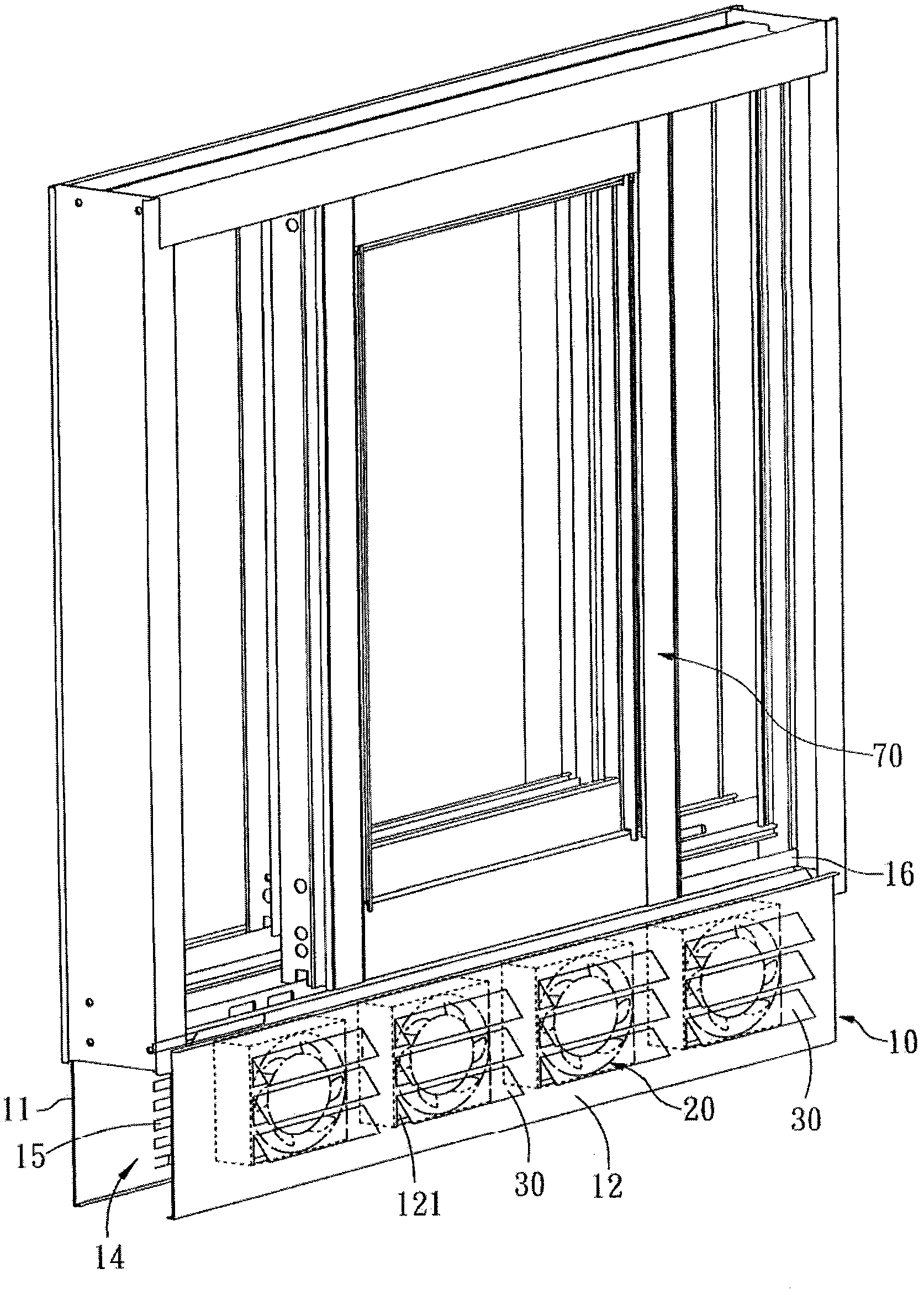
[0037] see image 3 and Figure 4 , which is a preferred embodiment of the present invention, a door and window frame structure with a ventilation fan includes an outer frame body 10, a ventilation fan 20, at least one rain shield 30 and a switch control rod 40, in this embodiment Among them, the outer frame body 10 is the outer frame of a horizontally drawn window, and the outer frame body 10 has a first side plate 11, a second side plate 12 opposite to the first side plate 11, a The upper supporting plate 13 of the first side plate 11 and the second side plate 12, an accommodating space 14 between the first side plate 11 and the second side plate 12, at least one formed on the first side plate 11 ventilation holes 15 and at least one movable frame guide rail 16. In this embodiment, the first side plate 11 and the second side plate 12 correspond to the indoor side and the outdoor side respectively, and the second side plate 12 has at least one connecting The opening 121 of ...


PUM


Abstract

The invention provides a door and window outer frame structure with a ventilation fan. The structure comprises an outer frame body and a ventilating fan, the outer frame body has a first side plate, a second side plate arranged opposite to the first side plate, and an accommodation space located between the first side plate and the second side plate and at least one ventilation hole formed in the first side plate, and the ventilation fan is installed in the accommodation space of the outer frame body, and is corresponding to the ventilation hole.

Description

technical field [0001] The invention relates to a door and window outer frame, in particular to a door and window outer frame structure with a ventilation fan. Background technique [0002] Such as figure 1 As shown, the known door and window structure includes an outer frame F, an outer movable frame M1, an inner movable frame M2 and a screen window W, and in order to increase the ventilation effect, it is mostly equipped with an active ventilation structure V, and the known The active ventilation structure V is a fan. However, when the active ventilation structure V is installed on the inner movable frame M2, its ventilation effect will be greatly reduced due to the obstruction of the screen window W. Therefore, at present, the active ventilation structure V is installed on the outer movable frame M2. Box M1 is the main one. However, please refer to figure 1 , when the active ventilation structure V is installed on an outdoor side S1 of the outer movable frame M1, the ...

Claims


Application Information

Patent Timeline
IPC IPC(8): E06B7/02E06B7/10E06B7/26G08B21/18
Inventor 周国忠
Owner TAROKO DOOR & WINDOW TECH
Why Eureka
Try Eureka