
Novel floor lamp structure

A lamp, a new type of technology, applied in the direction of lighting devices, independent lighting devices, electric light sources, etc., can solve the problems of rigid structure and achieve the effect of novel structure

Inactive Publication Date: 2013-03-20
YANGZHOU YONGPENG ELECTRONICS
View PDF0 Cites 1 Cited by
  • Summary
  • Abstract
  • Description
  • Claims
  • Application Information

AI Technical Summary

Problems solved by technology

The existing floor lamps have a rigid structure and cannot fully meet the needs of modern people

Method used


Image

  • Novel floor lamp structure

Examples


Embodiment Construction

[0011] The preferred embodiments of the present invention will be described in detail below in conjunction with the accompanying drawings, so that the advantages and features of the present invention can be more easily understood by those skilled in the art, so as to define the protection scope of the present invention more clearly.

[0012] see figure 1 , the embodiment of the present invention includes:

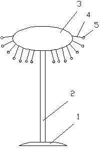
[0013] A new type of floor lamp structure, comprising: a base frame 1, a support rod 2 is fixedly installed on the base frame 1, a metal disc 3 is fixedly installed on the upper end of the support rod 2, and a metal disc 3 is evenly arranged around the metal disc 3. A plurality of connecting rods 4 , the connecting rods 4 are movably connected with the metal disc 3 , and bulbs 5 are arranged at the ends of the connecting rods 4 .

[0014] The connecting rod 4 is connected to the metal disc 3 through a hinge.

[0015] The connecting rod 4 can rotate 180 degrees.

[0016] ...


PUM


Abstract

The invention discloses a novel floor lamp structure which comprises a bottom frame. A support rod is fixedly mounted on the bottom frame, a metal round disc is fixedly mounted at the upper end of the support rod, multiple connecting rods are evenly arranged on the periphery of the metal round disc and movably connected with the metal round disc, and a bulb is mounted at the end portion of each connecting rod. Through the method, the novel floor lamp structure is novel, flexible and changeable, and a user can change the lamp structure freely according to the aesthetic point of view of the user so that different visual effects can be achieved.

Description

technical field [0001] The invention relates to the field of lamps, in particular to a novel floor lamp structure. Background technique [0002] Floor lamps are widely used in many home decorations. The floor lamp has soft light and gives people a warm feeling, which is deeply loved by people. The floor lamp can be placed in the living room or in the bedroom. It not only has the function of lighting, but also can decorate the room, killing two birds with one stone. Existing floor lamps have a rigid structure and cannot fully meet the needs of modern people. Contents of the invention [0003] The technical problem mainly solved by the present invention is to provide a novel floor lamp structure, which can solve the defects existing in the prior art, and has a novel and flexible structure. [0004] In order to solve the above technical problems, a technical solution adopted by the present invention is to provide a novel floor lamp structure, including: a base frame, a sup...

Claims


Application Information

Patent Timeline
IPC IPC(8): F21S6/00F21V21/116
Inventor 韦玉山
Owner YANGZHOU YONGPENG ELECTRONICS
Learn More