Display panel and display device

A display panel and display device technology, which is applied to identification devices, instruments, calculations, etc., can solve problems that affect users' use, considerable weight, and inconvenient use

Inactive Publication Date: 2014-11-26
BOE TECH GRP CO LTD
View PDF16 Cites 1 Cited by
  • Summary
  • Abstract
  • Description
  • Claims
  • Application Information

AI Technical Summary

Problems solved by technology

[0004] But existing flat-panel display still can't satisfy people's use demand to a greater extent
For example, the existing portable flat-panel displays only meet the requirements of lighter weight, and the function of being able to surf the Internet anytime, anywhere also needs to be realized in an environment where there is a wireless network anytime, anywhere. unrealistic
Or you need to insert a wireless network card into the corresponding card slot reserved in the flat-panel display to realize Internet access anytime and anywhere. However, the corresponding reserved card slot occupies a large area of ​​the whole machine, which is not conducive to realizing a thinner flat-panel display.
[0005] In addition, the existing flat-panel display uses a wired rechargeable battery, which requires a socket and a connecting line, which is very inconvenient to use
When the pre-charged battery is used up and cannot be charged in time, the flat-panel display cannot work, which greatly affects the user's use
Moreover, the existing wired rechargeable batteries often occupy a large space of the flat panel display, and the weight is considerable, which is not conducive to realizing a thinner and lighter flat panel display

Method used


Image

  • Display panel and display device
  • Display panel and display device

Examples


Embodiment 1

[0025] Embodiment 1: A display panel with a wireless router.

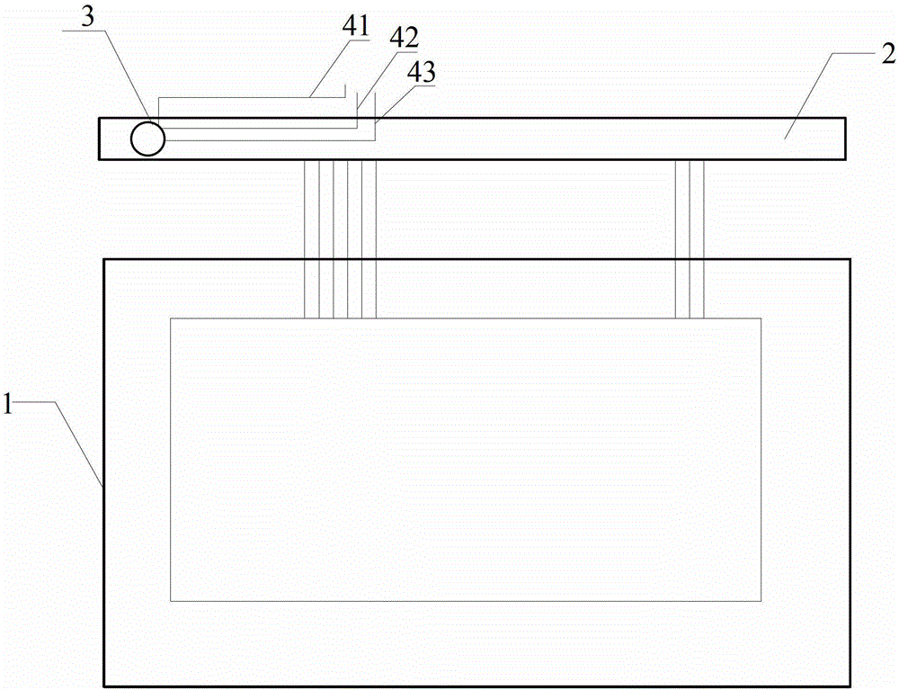
[0026] See figure 1 , Is a schematic top view of the array substrate and PCB structure in the display panel provided by the embodiment of the present invention.

[0027] Such as figure 1 As shown, a display panel provided by an embodiment of the present invention includes: an array substrate 1 and a PCB2, and a wireless router 3 arranged on the PCB2.

[0028] In a specific implementation process, the wireless router 3 may be soldered or glued on the PCB 2.

[0029] The PCB2 has leads connecting the wireless router 3 and the PCB2.

[0030] Preferably, the lead wire is connected to the wireless router 3 and the PCB 2 by welding.

[0031] Preferably, the leads include a power lead 41, a data input lead 42, and a data output lead 43.

[0032] In the embodiment of the present invention, a wireless router is arranged on the PCB connected to the array substrate to reduce the space of the whole machine and realize a lighter and thinne...

Embodiment 2

[0033] The second embodiment: a display panel with a wireless router and a wireless charger.

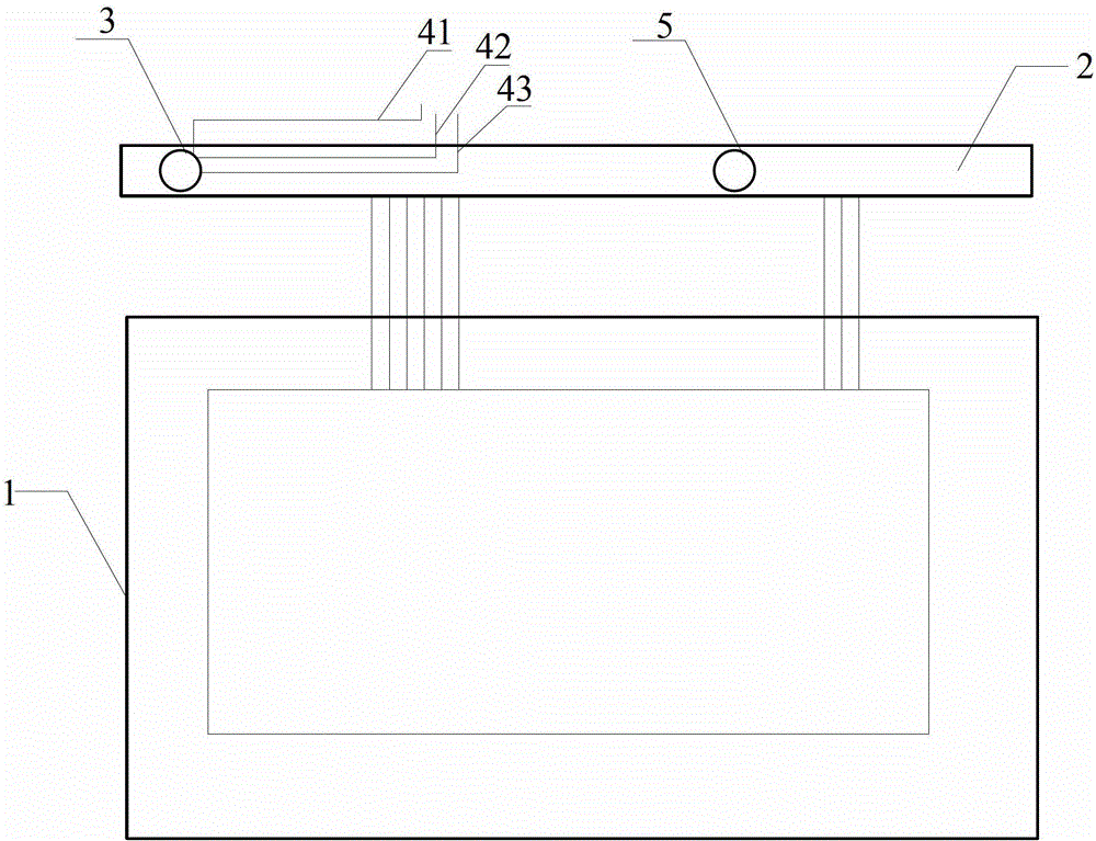
[0034] See figure 2 In the second embodiment of the present invention, a wireless charger 5 is added on the basis of the first embodiment.

[0035] Such as figure 2 The display panel provided in the second embodiment includes: an array substrate 1 and a PCB2, a wireless router 3 arranged on the PCB2, and a wireless charger 5 arranged on the PCB2.

[0036] The wireless charger 5 is one or more resonance devices, or one or more electromagnetic coils.

[0037] The wireless charger provided by the embodiment of the present invention does not require a socket and a connecting wire. Convenient to carry, charge at any time, no need to worry about the possibility of sudden power failure.

[0038] The following specifically describes the principle of implementing the wireless charger in the second embodiment of the present invention.

[0039] First, explain the principle that the wireless charger i...


PUM


Abstract

Embodiments of the present invention disclose a display panel and a display device, the display panel comprising: a display screen (1), comprising: an array substrate; an opposed substrate, cell-assembled with the array substrate to form the display screen; a circuit board (2), provided with a control circuit (5) for controlling the display screen thereon; and a wireless network adapter (3), receiving signals via a wireless network.

Description

Technical field [0001] The present invention relates to the field of display technology, in particular to a display panel and a display device. Background technique [0002] Flat panel displays refer to display devices with a ratio of the length of the diagonal of the display screen to the thickness of the whole machine greater than 4:1, including liquid crystal displays (LCD), organic light emission displays (Organic Light Emitting Diode, OLED), etc. . [0003] Flat panel displays have gradually become the mainstream in the display field due to their lightness, thinness, low power consumption, high luminous brightness, and wide viewing angles. As people’s requirements for portable flat panel displays gradually increase, flat panel displays that are lighter, thinner, and more convenient to carry are favored by people. [0004] However, the existing flat panel displays cannot meet people's use needs to a greater extent. For example, the existing portable flat-panel display only mee...

Claims


Application Information

Patent Timeline
Patent Type & Authority Patents(China)
IPC IPC(8): G09F9/30
CPCG06F1/1637G02F1/1333G06F1/182H04M2250/06G06F1/1626G06F1/16G06F1/18G09F9/00
Inventor 王东升董友梅张弥
Owner BOE TECH GRP CO LTD
Why Eureka
Try Eureka