Differential flow signal collector

A signal collector and split flow technology, applied in the direction of liquid/fluid solid measurement, instruments, measuring devices, etc., can solve the problems of measurement equipment error superposition, high failure rate, complex structure, etc., to reduce acquisition errors and ensure accuracy , the effect is obvious

Inactive Publication Date: 2011-12-21
CHONGQING AOKLAND MEDICAL EQUIP RES
View PDF3 Cites 0 Cited by
  • Summary
  • Abstract
  • Description
  • Claims
  • Application Information

AI Technical Summary

Problems solved by technology

Even if it is the same model and the same batch of equipment, it is impossible to be exactly the same, and the errors of the two measuring equipment will still be superimposed
[0004] Secondly, the structure using two devices combined to measure is more complicated than the structure using only one device, and the failure rate is also higher
For example, assuming that the failure rate of a single measuring device is 10‰, when two devices are used, if any one device fails, the whole machine will fail, so the failure rate is 10‰+(1-10‰)*10‰=19.9‰, if There are more components and more complex structures, and the failure rate will further increase

Method used


Image

  • Differential flow signal collector
  • Differential flow signal collector
  • Differential flow signal collector

Examples


Embodiment Construction

[0023] Below in conjunction with accompanying drawing, the present invention is described in detail.

[0024] In order to make the object, technical solution and advantages of the present invention clearer, the present invention will be further described in detail below in conjunction with the accompanying drawings and embodiments. It should be understood that the specific embodiments described here are only used to explain the present invention, not to limit the present invention.

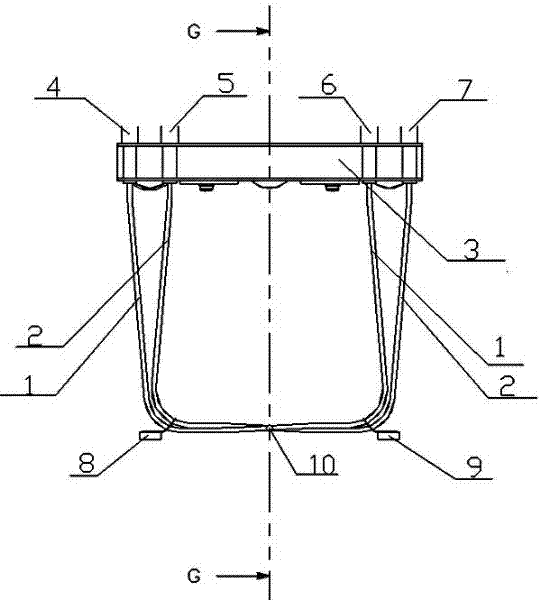
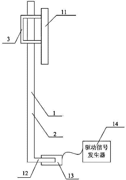
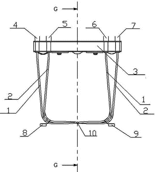
[0025] Such as figure 1 As shown, the differential flow signal collector includes a first pipeline 1, a second pipeline 2, a base 3, a first signal collector 8, a second signal collector 9, a vibration device 10 and a signal processing device 11, wherein the first The pipeline 1 and the second pipeline 2 extend side by side through one end of the base 3 to the other end of the base 3, and the first pipeline 1 and the second pipeline 2 are respectively symmetrical in structure along a direction pe...


PUM


Abstract

The invention discloses a differential flow signal collector, which belongs to the field of signal collection. The differential flow signal collector includes a first pipeline and a second pipeline, a base, a vibrating device, a first signal collector and a second signal collector with the same structure and are respectively symmetrical. Two fluids flow into the two pipelines from different directions. , and the two pipelines vibrate at the same frequency under the action of the vibrating device, and the two collectors are respectively arranged at positions equal to the distance from the two pipelines to the vibrating device. Through the invention, the influence of the device on the fluid flowing through the two pipelines is reduced to the minimum, thereby ensuring the accuracy of flow signal collection of two different fluids.

Description

technical field [0001] The invention relates to a flow signal collector, in particular to a differential flow signal collector. Background technique [0002] In the measurement of ultrafiltration in hemodialysis treatment, the flow correction of multi-liquid pipelines, etc., it is necessary to measure the flow difference of two liquids (or fluids), but the flow difference measurement method currently used is to measure the flow values ​​of different pipelines separately , and then compare the two flow values ​​to obtain the flow difference. [0003] First of all, two measuring devices are used in this flow difference method, and the flow difference is obtained indirectly based on the single-channel flow value measured by the two measuring devices respectively, so if the two measuring devices are inconsistent, the measured value will be increased. Error, that is, the superposition of errors. For example, two devices with an accuracy of ±5%, when subtracting their measuremen...

Claims


Application Information

Patent Timeline
Patent Type & Authority Applications(China)
IPC IPC(8): G01F15/00
Inventor 雷鸣陈竹
Owner CHONGQING AOKLAND MEDICAL EQUIP RES
Why Eureka
Try Eureka