Jig for positioning steel sheet, steel sheet positioning method and electronic product

A positioning method and steel sheet technology, applied in the direction of electrical equipment casing/cabinet/drawer, electrical components, casing/cabinet/drawer parts, etc., can solve the problems of large horizontal space requirements and complex molds

Active Publication Date: 2022-03-18
HONOR DEVICE CO LTD
View PDF12 Cites 0 Cited by
  • Summary
  • Abstract
  • Description
  • Claims
  • Application Information

AI Technical Summary

Problems solved by technology

For example, when the steel sheet is positioned through the structural form of the positioning hole (slot), the horizontal space requirements of the electronic product are large, and the structure of the positioning hole (slot) is designed for different electronic products, and the mold is complicated.

Method used


Image

  • Jig for positioning steel sheet, steel sheet positioning method and electronic product
  • Jig for positioning steel sheet, steel sheet positioning method and electronic product
  • Jig for positioning steel sheet, steel sheet positioning method and electronic product

Examples


Embodiment 1

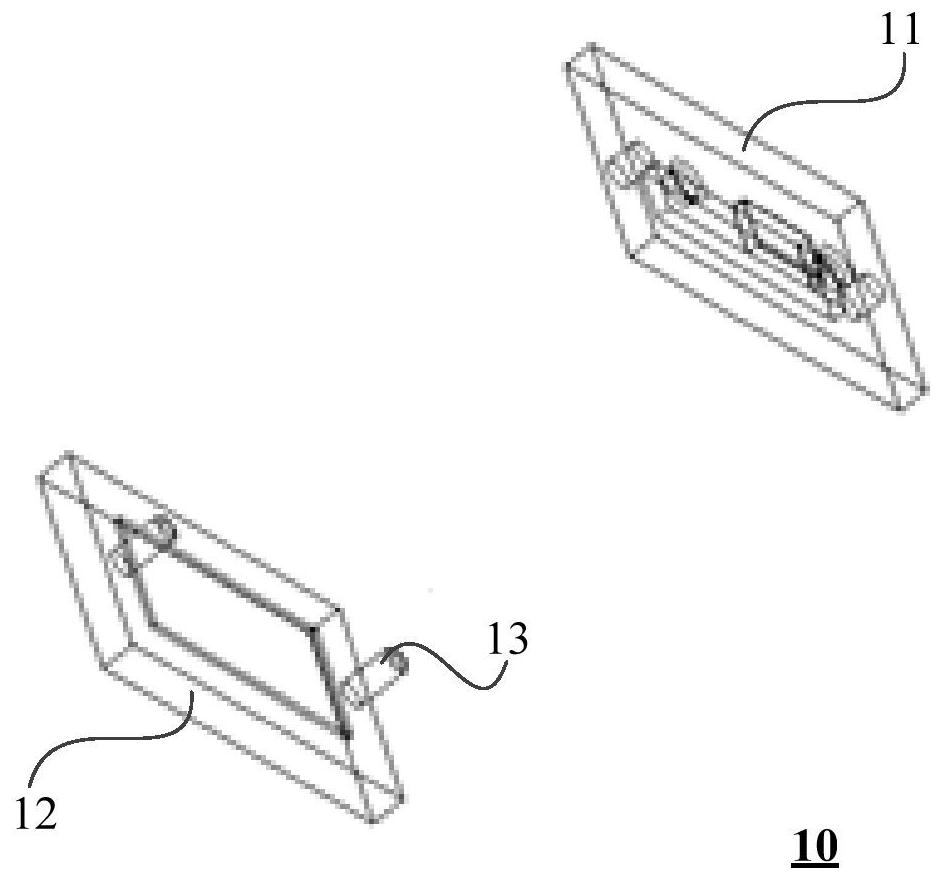
[0077] figure 1 An exploded view of a jig for positioning steel sheets provided by an embodiment of the present application. This embodiment provides a jig for positioning steel sheets, such as figure 1 As shown, the jig 10 includes: an upper cover 11 , a lower cover 12 and a positioning guide 13 .

[0078] Wherein, the upper cover plate 11 is provided with a first groove (not shown), and the first groove is used for positioning the steel sheet. A second groove (not shown) is provided on the lower cover plate 12, and the second groove is used for positioning and fixing the substrate. The lower cover plate 12 cooperates with the upper cover plate 11 through the positioning guide 13 to position the steel sheet to the compacted body located on the upper part of the compacted matrix.

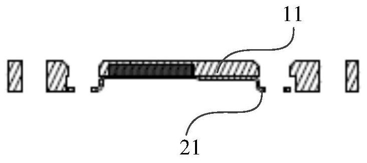
[0079] In actual application, the steel sheet 21 is fixed and positioned on the upper cover plate 11, such as Figure 2A , Figure 2B and Figure 2C shown. in, Figure 2A A front view cross-...

Embodiment 2

[0087] On the basis of the above embodiments, in a possible implementation manner, the positioning guide 13 is arranged on the lower cover plate 12, such as figure 1 or Figure 3A , Figure 4A and so on. Or, the positioning guide 13 is independent of the lower cover 12 and the upper cover 11, and the positioning guide 13 is connected with the lower cover 12 by welding, or the positioning guide 13 is connected with the upper cover 11 by welding. .

[0088] When the positioning guide 13 is disposed on the lower cover 12 , the positioning guide 13 and the lower cover 12 can be integrally formed. In this case, optionally, the upper cover plate 11 is provided with a positioning portion that cooperates with the positioning guide 13 . Wherein, the positioning guide member 13 is, for example, a positioning guide post, etc. At this time, the upper cover plate 11 is provided with structures such as a positioning hole or a positioning groove that cooperate with the positioning guide ...

Embodiment 3

[0091] still refer to Figure 4A and Figure 4B , the first groove 22 is provided with an adsorption device 41 , and the upper cover plate 11 is fixed and positioned by the adsorption device 41 to position the steel sheet 21 . Wherein, the adsorption device 41 may at least include any one of a magnet, an air suction device, and the like. That is to say, the adsorption device 41 in the embodiment of the present application includes but not limited to a magnet and a suction device.

[0092] When the adsorption device 41 is a magnet, if the fastener 42 used to fix the steel sheet 21 and the compressed body 32 is a magnetic fastener, the magnetic fastener may cause a positional deviation due to the magnetic attraction force, so , the fastener 42 at this time may specifically be a non-magnetic fastener, such as a non-magnetic screw, or a fastener including a non-magnetic bolt and a non-magnetic nut, and the like. By setting the fasteners as non-magnetic fasteners, the influence ...


PUM


Abstract

Embodiments of the present application provide a jig for positioning a steel sheet, a steel sheet positioning method, and an electronic product. The jig includes: an upper cover, a lower cover and a positioning guide; a first groove is arranged on the upper cover, and the first groove is used for positioning the steel sheet; a second groove is arranged on the lower cover, and the second groove It is used to position the compacted matrix; the lower cover plate and the upper cover plate cooperate through positioning guides to position the steel sheet to the compacted solid located on the upper part of the compacted matrix. In the embodiment of the present application, the steel sheet is positioned to the solid to be pressed through the third-party tool of the jig, which avoids the problem of high space requirements for the whole machine when directly positioning the steel sheet and the solid to be pressed, and can also realize the positioning of the steel sheet. Save the overall space of electronic products.

Description

technical field [0001] The embodiments of the present application relate to assembly technologies, and in particular to a jig for positioning steel sheets, a steel sheet positioning method, and electronic products. Background technique [0002] With the development of communication technology, the space layout of electronic products is becoming more and more compact. For example, the industry reduces the thickness of electronic products by designing steel sheets in local areas of electronic products. [0003] At present, the positioning of the steel sheet in the electronic product is mainly realized through structural forms such as positioning holes (slots) and steel sheet folded edges, but these structural forms have higher requirements on the overall space of the electronic product. For example, when the steel sheet is positioned through the structural form of the positioning hole (slot), the horizontal space requirement of the electronic product is large, and the structu...

Claims


Application Information

Patent Timeline
Patent Type & Authority Patents(China)
IPC IPC(8): H05K5/02
CPCH05K5/0217
Inventor 岳永保张光永
Owner HONOR DEVICE CO LTD
Why Eureka
Try Eureka