Compact high-resolution optical fiber imaging system

A high-resolution, imaging system technology, applied in the directions of light guides, optics, optical components, etc., can solve the problems of increased light loss, small magnification of the imaging part, and large conjugate distance, so as to reduce the machine space and improve the imaging resolution. , The effect of reducing the welding loss

Inactive Publication Date: 2020-04-17
中电科思仪科技(安徽)有限公司
View PDF6 Cites 0 Cited by
  • Summary
  • Abstract
  • Description
  • Claims
  • Application Information

AI Technical Summary

Problems solved by technology

[0004] The published invention patent CN 107121727A proposes a fiber core identification imaging system. The illumination part adopts the collimation reflection type, which increases the light loss and needs to increase the positioning space of the lighting lamp in the fuselage. The imaging part has small magnification and poor resolution of the lens. The high restrictive factors cannot meet the needs of today's market for small and exquisite optical fiber imaging systems of fusion splicing machines and clear pictures.
The published invention patent CN102998788A proposes an imaging system for an optical fiber fusion splicer, which has a large magnification, but the conjugate distance is large, which increases the assembly space of the rack, and at the same time, the imaging resolution is low, which affects the judgment of the fiber core by the software and the customer's visual perception of the image

Method used


Image

  • Compact high-resolution optical fiber imaging system
  • Compact high-resolution optical fiber imaging system
  • Compact high-resolution optical fiber imaging system

Examples


Embodiment Construction

[0027] Below in conjunction with accompanying drawing and specific embodiment the present invention is described in further detail:

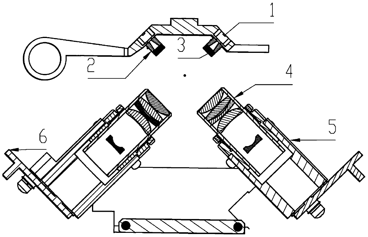
[0028] Such as figure 1 As shown in Fig. 1, a compact high-resolution optical fiber imaging system includes two parts: optical fiber illumination optical path Ⅰ and optical fiber imaging optical path Ⅱ.

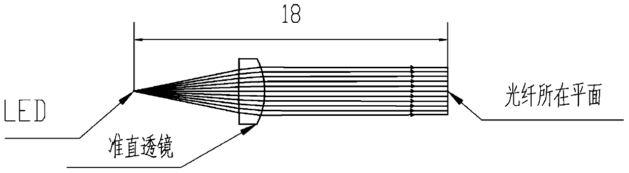
[0029] The optical fiber lighting path I adopts the direct lighting method, which includes the LED light source 1 and the light guide tube 2 respectively. Compared with the traditional reflective lighting method, it can reduce the loss of light energy caused by the long reflection path. Because the LED light source 1 emits light The area is very small, here we can approximate it as a point light source, the light guide tube 2 is cylindrical, the length is 7.5mm, the internal light hole is tapered, used for the transmission of the light beam, the front end is attached to the light source, and the rear end is fixed. Straight lens 3, the radial c...


PUM

PropertyMeasurementUnit
lengthaaaaaaaaaa

Abstract

The invention discloses a compact high-resolution optical fiber imaging system, and belongs to the field of optical fiber fusion splicers. The compact high-resolution optical fiber imaging system comprises a lighting part and an imaging part, the lighting part adopts a direct structure design, a collimating lens is used for modulating an led light source to obtain parallel light beams in a short optical path, the interference caused by stray light is weakened, and the imaging quality is favorably improved; the imaging part is mainly composed of a microscope objective, a lens cone and a camera,amplification imaging of the to-be-fused optical fiber can be achieved within a short conjugate distance, and pictures are clear. According to the optical fiber imaging system, high image quality isachieved, meanwhile, the size of the fusion splicer can be reduced to a certain degree, and the requirement for portability of the current fusion splicer market is met.

Description

technical field [0001] The invention belongs to the field of optical fiber fusion splicing machines, and in particular relates to a compact high-resolution optical fiber imaging system. Background technique [0002] In today's information age, with the rapid development of the Internet of Things, optical fiber communication has become the main force of information transmission. The popularization of wired optical networks requires a large number of optical fiber connections. As the leading instrument (equipment) for optical fiber connection, optical fiber fusion splicers are responsible for important role. [0003] The key performance index of the optical fiber fusion splicer is the optical power loss of the fusion splicing point. Only a high-quality fusion splicing point can ensure the long-distance transmission of optical signals. To ensure the quality of fusion splicing, it is necessary to complete the physical core of the optical fiber at both ends. Accurate docking , w...

Claims


Application Information

Patent Timeline
Patent Type & Authority Applications(China)
IPC IPC(8): G02B6/255G02B27/30G02B27/00G02B13/00
CPCG02B6/2555G02B13/0015G02B27/00G02B27/30
Inventor 任晓楠杨小光曹雨贺永亮彭杰叶旭李博
Owner 中电科思仪科技(安徽)有限公司
Why Eureka
Try Eureka