Signal transmission method, signal decoding method, device and system
A signal transmission and signal technology, applied in the field of communication, can solve the problems of complex and difficult to implement interference suppression methods between cells, and achieve the effect of easy operation and reduced number of iterations
- Summary
- Abstract
- Description
- Claims
- Application Information
AI Technical Summary
Problems solved by technology
Method used
Image

Examples
Embodiment 1
[0032] The embodiment of the present invention is applied to a CoMP system. When the system performs signal transmission, the following situations may occur:
[0033] Suppose there are K eNBs, each cell serves only one UE, and the UE served by each cell uses the same time-frequency resource, each eNB has M transmit antennas, and the kth user includes N k root receiving antenna, user k needs to transmit m k an independent data stream. An eNB k (k=1, 2, ..., K) the signal sent can be expressed as an M-dimensional column vector W k the s k , where W k M×m for user k k dimensional precoding matrix, and satisfy tr(Wk W k H ) = m k , tr() means trace operation, superscript H means conjugate transpose operation, s k is user k's m k Dimensional emission symbol vector.
[0034] In a CoMP system, how to restore the signal sent by the base station at the receiving end is typical. Usually, when discussing the precoding algorithm, in addition to obtaining the precoding matrix of...
Embodiment 2
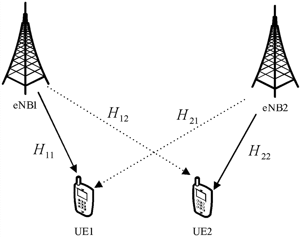
[0092] This embodiment provides a method for implementing CoMP precoding in the case of two cells, and the base stations in this method are eNBs 1 and eNB 2 ; eNB 1 and eNB 2 The number of transmit antennas is 4, UE 1 and UE 2 The receiving antennas are all 2, and the number of layers of each UE is the above m k is 2, namely K=2, M=4, N k = 2, m k =2. like Figure 4 As shown, the method includes the following steps:
[0093] Step S402: Estimating the channel matrix between the base station and the users in the cell;
[0094] Estimated base station eNB 1 with UE in this cell 1 The channel matrix H between 11 , base station eNB 1 UE in neighboring cells 2 The channel matrix H between 21 , base station eNB 2 with UE in this cell 2 The channel matrix H between 22 , base station eNB 2 UE in neighboring cells 1 The channel matrix H between 12 .
[0095] Step S404: Singular value decomposition is performed on the channel matrix of each user to obtain the initial...
Embodiment 3
[0122] This embodiment provides a signal sending device, which can be set on a base station. like Figure 5 As shown, the device includes the following modules:
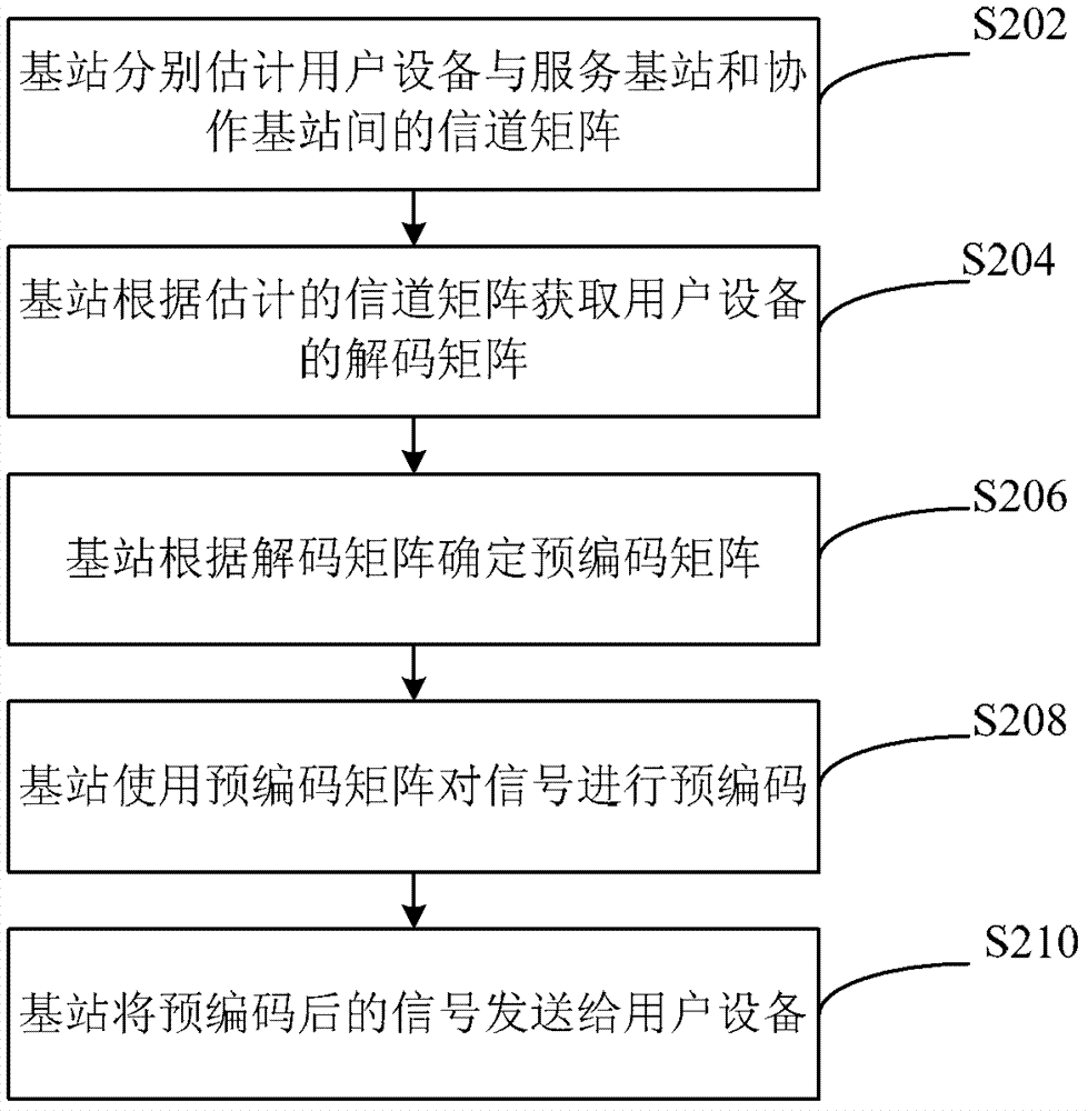
[0123] A channel matrix estimation module 51, configured to estimate the channel matrix between the user equipment and the serving base station and the coordinated base station respectively;
[0124] The decoding matrix acquisition module 52 is connected to the channel matrix estimation module 51, and is used to acquire the decoding matrix of the user equipment according to the channel matrix estimated by the channel matrix estimation module 51;
[0125] The precoding matrix determining module 53 is connected with the decoding matrix obtaining module 52, and is used to determine the precoding matrix according to the decoding matrix obtained by the decoding matrix obtaining module 52;
[0126] The precoding module 54 is connected to the precoding matrix determining module 53, and is used to precode the signal using ...
PUM
 Abstract
Description
Claims
Application Information
 - R&D Engineer
- R&D Manager
- IP Professional
- Industry Leading Data Capabilities
- Powerful AI technology
- Patent DNA Extraction
Browse by: Latest US Patents, China's latest patents, Technical Efficacy Thesaurus, Application Domain, Technology Topic.
© 2024 PatSnap. All rights reserved.Legal|Privacy policy|Modern Slavery Act Transparency Statement|Sitemap