Target radar cross section measuring and calibrating processing method

A radar cross-section and target technology, applied in radio wave measurement systems, instruments, etc., can solve the problem of increased target RCS measurement error

Active Publication Date: 2013-03-27
BEIHANG UNIV
View PDF3 Cites 31 Cited by
  • Summary
  • Abstract
  • Description
  • Claims
  • Application Information

AI Technical Summary

Problems solved by technology

[0007] The present invention provides a target radar scattering cross-section measurement and calibration processing method, which is used to solve the problem that the electrical performance paramete

Method used


Image

  • Target radar cross section measuring and calibrating processing method
  • Target radar cross section measuring and calibrating processing method
  • Target radar cross section measuring and calibrating processing method

Examples


Embodiment Construction

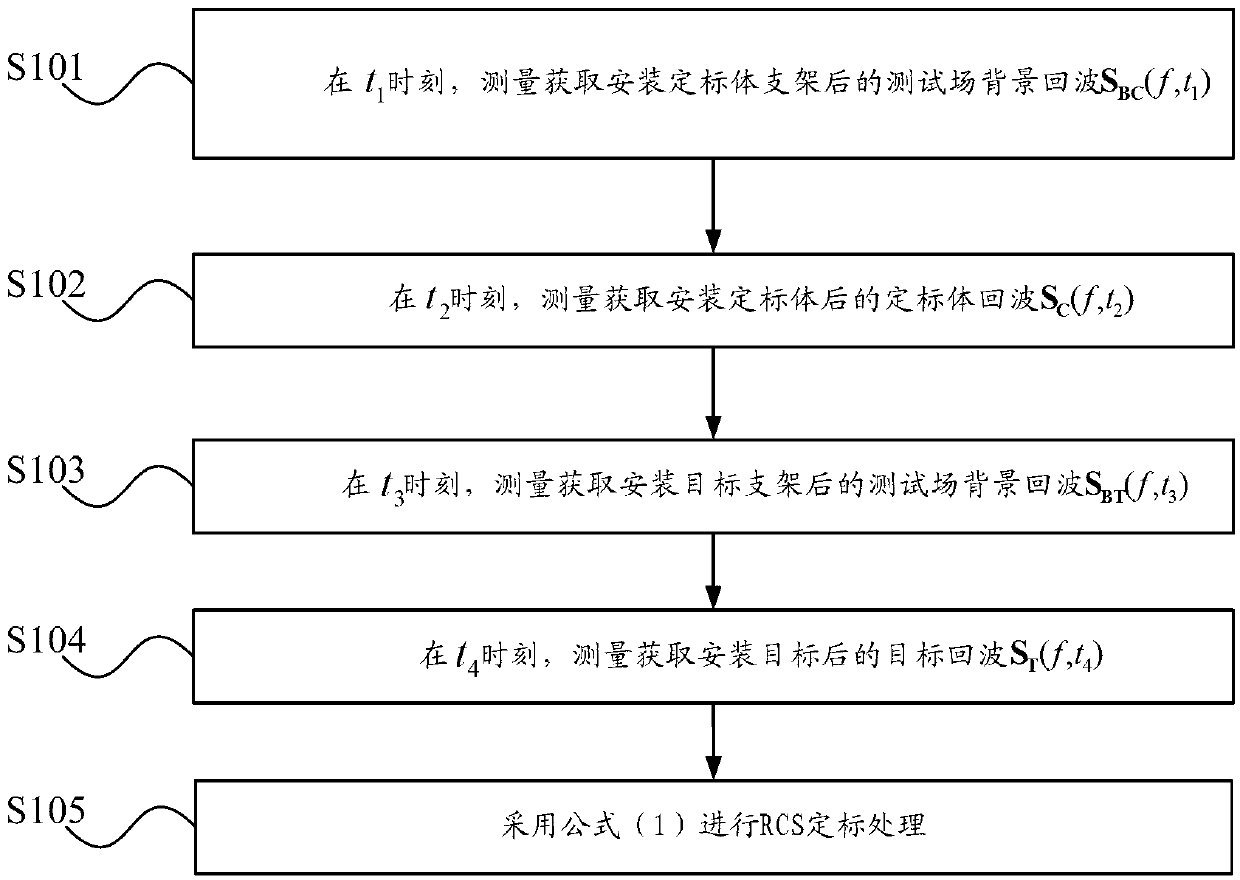
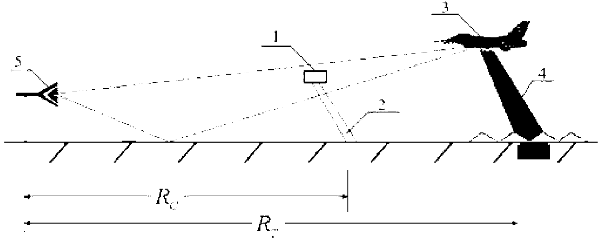
[0040] figure 1 It is a flow chart of a method embodiment of target radar cross section measurement and calibration processing in the present invention, figure 2 for figure 1 The schematic diagram of the position relationship of target radar scattering cross section measurement in the shown embodiment, combined with figure 1 , figure 2 , the method, including:

[0041] S101, at t 1 time, measure and obtain the background echo S of the test field after the calibration body bracket 2 is installed BC (f,t 1 ), S BC (f,t 1 )=H C (f,t 1 )·B C (f,t 1 );

[0042] where H C (f, t) is the transfer function of the measurement system-test field when measuring the target, B C (f, t) is the inherent background scattering when measuring the target, and it changes with time t.

[0043] S102, at t 2 time, measure and acquire the echo S of the calibration body after installing the calibration body 1 C (f,t 2 );

[0044] Specifically, it is assumed that the RCS measurement ...


PUM


Abstract

The invention provides a target radar cross section measuring and calibrating processing method. The method includes measuring and acquiring a test field background echo SBC (f,t1) at the moment of t1 after a calibration member support is installed, wherein SBC (f, t) is equal to HC(f, t1) * BC (f, t1); measuring and acquiring a calibration member echo SC (f, t2) at the moment of t2 after a calibration member is installed; measuring and acquiring a test field background echo SBT (f, t3) at the moment of t3 after a target support is installed, wherein SBT (f, t3) is equal to HT(f, t3) * BT (f, t3); and measuring and acquiring a target echo ST (f, t4) at the moment of t4 after a target is installed. The formula (1) is used for performing calibrating processing. By means of the target radar cross section measuring and calibrating processing method, the problem that measuring calibrating errors caused by many time varying factors in outfield testing are large can be solved.

Description

technical field [0001] The present invention relates to radar signal processing technology, in particular to a target radar cross section (Radar Cross Section, RCS for short) measurement and calibration processing method. Background technique [0002] RCS measurement technology is one of the important means to study target radar scattering characteristics. RCS can be determined according to the precise RCS value of the calibration object, the calibration constant under different distance conditions, and the echo signals of the radar target and the calibration object. At present, when measuring the echo signals of the radar target and the calibration body, it is usually necessary to use a metal bracket to support the radar target and the calibration body. [0003] In the prior art, the steps of RCS measurement are as follows: placing the measuring body bracket, and measuring the background echo B of the test field at this time C (f); Install the calibration body and measure...

Claims


Application Information

Patent Timeline
IPC IPC(8): G01S7/41
Inventor 许小剑
Owner BEIHANG UNIV
Why Eureka
Try Eureka