Management method of a computer cache system

The technology of a cache system and management method, which is applied in the management field of computer cache systems, can solve problems such as increasing cache errors and reducing performance, and achieve the effects of reducing cache errors, ensuring stability, and having a wide range of applications

Active Publication Date: 2015-09-09
广东地球村计算机系统股份有限公司
View PDF10 Cites 0 Cited by
  • Summary
  • Abstract
  • Description
  • Claims
  • Application Information

AI Technical Summary

Problems solved by technology

[0004] The purpose of the present invention is to overcome the existing useful data in the CPU cache will be replaced by the prefetched content when the current CPU is prefetching, thereby increasing the defects of cache errors and reducing performance, and providing a method that can effectively solve the above defects A kind of management method of computer cache system

Method used


Image

  • Management method of a computer cache system
  • Management method of a computer cache system
  • Management method of a computer cache system

Examples


Embodiment 1

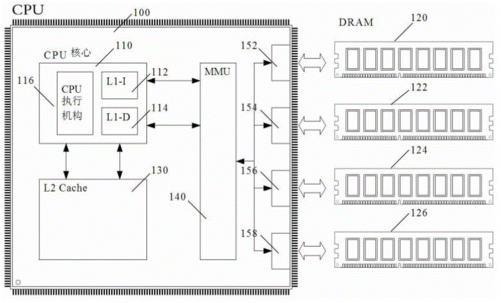
[0038] Such as Figure 1~3 As shown, the CPU independent chip 100 in the CPU system of the present invention integrates a CPU core 110, a secondary cache 130, a memory access controller MMU 140 and four memory channels. The CPU core 110 is built with a CPU execution unit 116 , a first-level instruction cache 112 (ie, L1-I Cache), and a first-level data cache 114 (ie, L1-D Cache). The secondary cache 130 directly exchanges data with the CPU core 110, and the four memory channels (i.e. memory channel one 152, memory channel two 154, memory channel three 156, and memory channel four 158) communicate with the memory access controller MMU 140 to accept its management instructions.

[0039] The memory access controller MMU 140 exchanges data with the instruction and data filling mechanism of the CPU core 110 . figure 1 The first cache of the independent CPU chip 100 in the CPU adopts a separate storage structure for instructions and data: instructions are stored in the first-level...

Embodiment 2

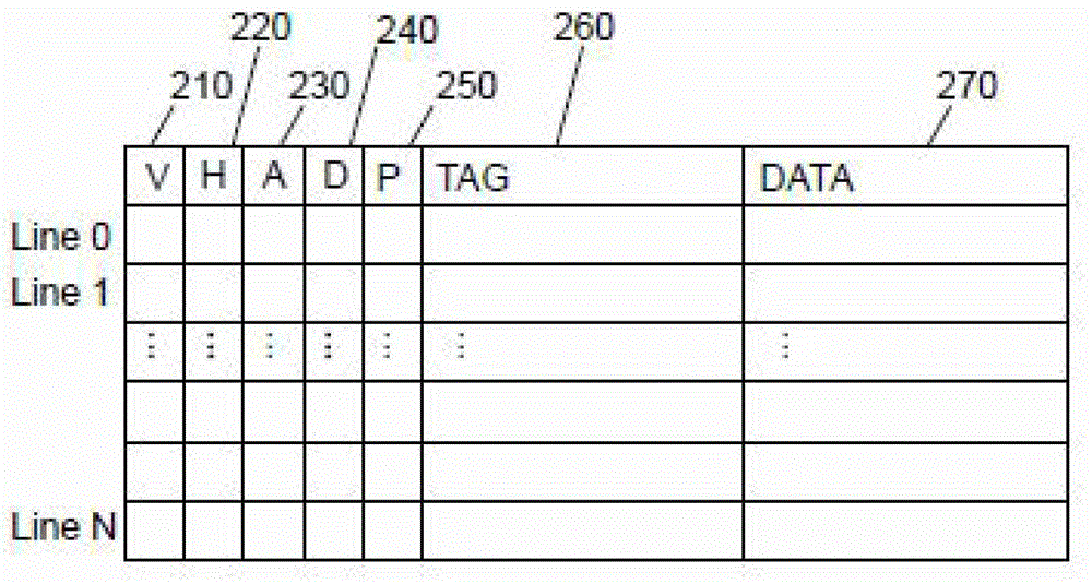
[0048] Such as Figure 4A , 5A As shown, each cache line in this embodiment has a TAG storage area 450 , a Data storage area 460 , and four identification bits: V identification bit 410 , H identification bit 420 , A identification bit 430 and D identification bit 440 . Wherein, the V flag 410 represents that the cache line is valid (Valid); the H flag 420 represents that the cache line has been hit (Hit), and when the cache line was initially loaded, the H flag 420 was set to zero, if the cache line Hit, then be set as 1; A flag bit 430 marks this cache line to have been allocated (Allocated) by replacement algorithm, and this flag bit is used for reminding replacement algorithm not to repeatedly allocate same cache line to be replaced; D flag bit 440 represents this cache line The content of has been changed (Dirty), and after being replaced out of the cache, the changed content needs to be written into the memory.

[0049] Compared with Embodiment 1, this embodiment diffe...

Embodiment 3

[0060] Such as Image 6 , 7 As shown, the cache line in this embodiment has a TAG storage area 670, a Data storage area 680, and 6 identification bits: a V identification bit 610, an H identification bit 620, an A identification bit 630, a D identification bit 640, and a P identification bit 650 and U identification bit 660.

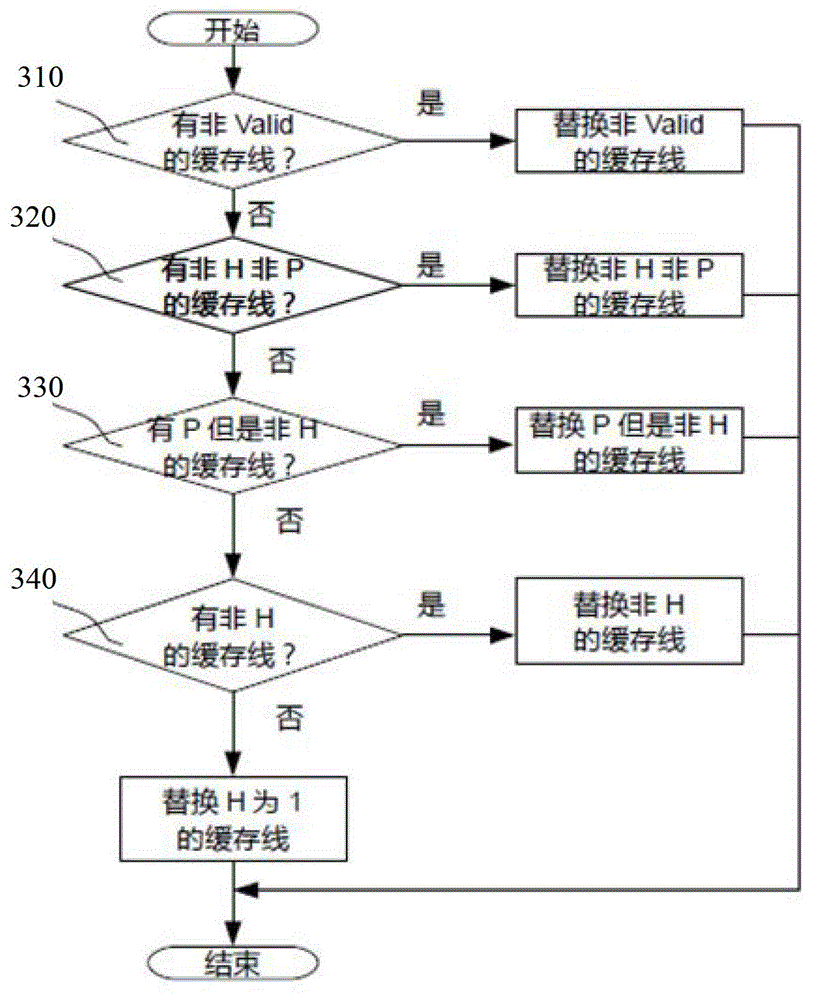
[0061] Wherein, the V flag 610 represents that the cache line is valid (Valid); the H flag 620 represents that the cache line has been hit (Hit), and when the cache line is initially loaded, the H flag 620 is set to zero, if the cache line Hit, then set to 1; A flag 630 indicates that the cache line has been allocated by the replacement algorithm (Allocated); D flag 640 indicates that the content of the cache line has been changed (Dirty), after being replaced out of the cache, need Write the changed content into memory; if the P flag 650 is 1, it means that the cache line is the prefetch (Prefetch) content, if it is zero, it means that the cache line ...


PUM


Abstract

The invention discloses a management method of a computer cache system. The method is characterized in that the cache system comprises more than one cache lines, each cache line comprises one or more data words and each cache line comprises a Hit identifier position, and the data word of the cache line is currently used or pre-taken. The management method comprises the following steps: when the cache line is loaded, configuring the Hit identifier position as 0; when the cache line is hit, configuring the Hit identifier position as 1; during replacement, firstly, replacing the cache line with the Hit identifier position as 0 and then replacing the cache line with the Hit identifier position as 1. According to the invention, the CPU (Central Processing Unit) system has the pre-taking capacity of command and data and can send a request to take the command data from the memory or other storage mechanisms to the CPU in advance before the command and data is actually used, so that the operational speed can be remarkably improved.

Description

technical field [0001] The invention relates to a management algorithm of a computer cache system, in particular to a management method of a CPU cache system. Background technique [0002] Currently, computer systems experience significant delays when accessing devices such as memory and other low-level storage devices such as hard disks and network devices. Taking memory access as an example, it takes about 100 nanoseconds to get the data after the CPU issues the access commands for data and instructions, which is equivalent to the time for the CPU core to execute hundreds of instructions. Since the CPU system has certain rules for the use of instructions and data, according to these rules, we can design various means to guess the instructions and data that the CPU will use, and prefetch these contents to the CPU in advance for backup. In this way, when the CPU wants to actually use these instructions and data, it does not need to wait and can obtain these instructions and...

Claims


Application Information

Patent Timeline
Patent Type & Authority Patents(China)
IPC IPC(8): G06F12/08G06F12/121
Inventor 邹阳王去非
Owner 广东地球村计算机系统股份有限公司
Why Eureka
Try Eureka