Management method for cache system of computer
A technology of a cache system and a management method, applied in the management field of computer cache systems, can solve problems such as increasing cache errors and reducing performance, and achieves the effects of reducing cache errors, ensuring stability, and having a wide range of use.
- Summary
- Abstract
- Description
- Claims
- Application Information
AI Technical Summary
Problems solved by technology
Method used
Image
Examples
Embodiment 1
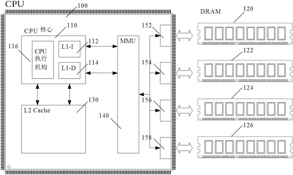
[0035] Such as Figure 1~3 As shown, the CPU independent chip 100 in the CPU system of the present invention integrates a CPU core 110, a secondary cache 130, a memory access controller MMU 140, and four memory channels. The CPU core 110 has a built-in CPU execution mechanism 116, a first-level instruction cache 112 (ie, L1-I Cache), and a first-level data cache 114 (ie, L1-D Cache). The second-level cache 130 directly exchanges data with the CPU core 110, and the four memory channels (ie, memory channel one 152, memory channel two 154, memory channel three 156, and memory channel four 158) are connected with the memory access controller MMU 140 is connected to accept its management instructions.
[0036] The memory access controller MMU 140 exchanges data with the instruction and data filling mechanism of the CPU core 110. figure 1 The first cache of the independent CPU chip 100 in the CPU adopts a structure of separate storage of instructions and data: instructions are stored ...
Embodiment 2
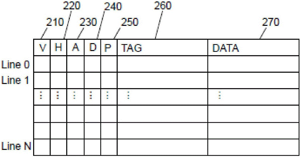
[0045] Such as Figure 4A , 5A As shown, each cache line in this embodiment has a TAG storage area 450, a Data storage area 460, and four identification bits: V identification bit 410, H identification bit 420, A identification bit 430 and D identification bit 440. Among them, the V flag 410 represents that the cache line is valid (Valid); the H flag 420 indicates that the cache line has been hit (Hit). When the cache line is initially loaded, the H flag 420 is set to zero. If it hits, it is set to 1. The A flag 430 indicates that the cache line has been allocated by the replacement algorithm (Allocated). This flag is used to remind the replacement algorithm not to repeatedly allocate the same cache line to be replaced; the D flag 440 indicates the cache line The content of has been changed (Dirty), after being replaced out of the cache, the changed content needs to be written into the memory.
[0046] Compared with Embodiment 1, the difference between this embodiment and Embodim...
Embodiment 3
[0057] Such as Image 6 , 7 As shown, the cache line in this embodiment has a TAG storage area 670, a Data storage area 680, and 6 identification bits: V identification bit 610, H identification bit 620, A identification bit 630, D identification bit 640, and P identification bit 650 and U mark 660.
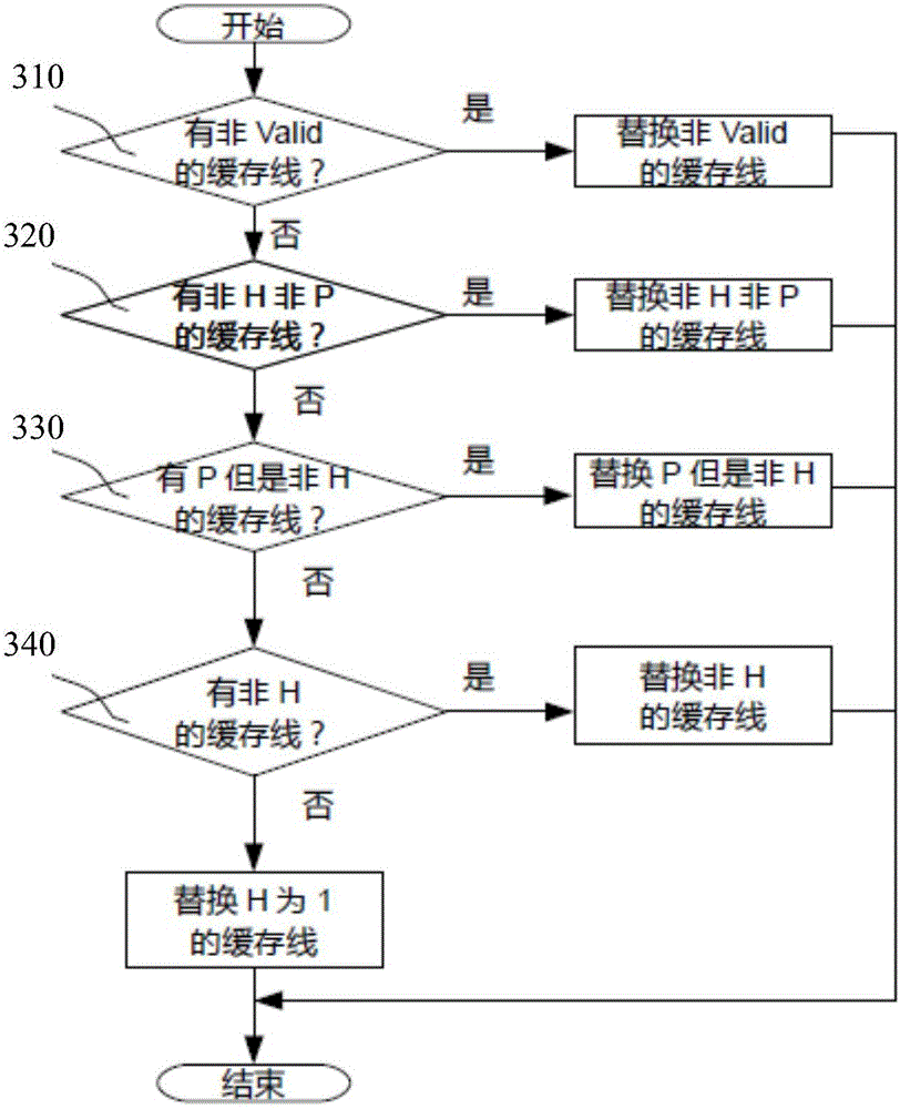
[0058] Wherein, the V flag 610 represents that the cache line is valid (Valid); the H flag 620 indicates that the cache line has been hit (Hit). When the cache line is initially loaded, the H flag 620 is set to zero. If it hits, it is set to 1. The A flag 630 indicates that the cache line has been allocated by the replacement algorithm (Allocated); the D flag 640 indicates that the content of the cache line has been changed (Dirty). After the cache is replaced, it needs to Write the changed content into the memory; if the P flag 650 is 1, it means that the cache line is prefetch content, if it is zero, it means the cache line is demand fetch content; the U flag 660 is in When the c...
PUM
 Abstract
Description
Claims
Application Information
 - R&D
- Intellectual Property
- Life Sciences
- Materials
- Tech Scout
- Unparalleled Data Quality
- Higher Quality Content
- 60% Fewer Hallucinations
Browse by: Latest US Patents, China's latest patents, Technical Efficacy Thesaurus, Application Domain, Technology Topic, Popular Technical Reports.
© 2025 PatSnap. All rights reserved.Legal|Privacy policy|Modern Slavery Act Transparency Statement|Sitemap|About US| Contact US: help@patsnap.com


