Meteorite crater matching method based on area ratio

A matching method and crater technology, applied in the field of image processing, can solve problems such as large image rotation, false matching, and mismatching

Inactive Publication Date: 2013-03-27
HARBIN INST OF TECH
View PDF1 Cites 12 Cited by
  • Summary
  • Abstract
  • Description
  • Claims
  • Application Information

AI Technical Summary

Problems solved by technology

[0007] The present invention proposes a crater matching method based on the area ratio in order to solve the problems of large rotation, scaling and deformation of the image in the existing crater matching method.

Method used


Image

  • Meteorite crater matching method based on area ratio
  • Meteorite crater matching method based on area ratio
  • Meteorite crater matching method based on area ratio

Examples


Embodiment approach 1

[0020] Specifically embodiment one: a kind of crater matching method based on the area ratio of the present embodiment, the steps are as follows:

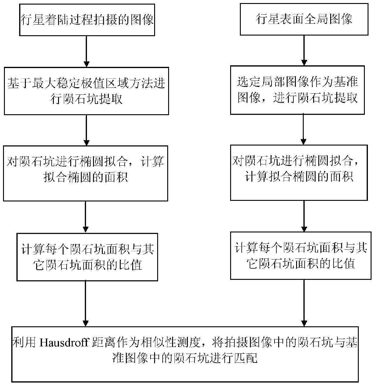
[0021] Step 1: According to the initial position, attitude and camera parameters of the planetary lander during the landing process, take an image of the surface of the target celestial body, and select a partial image in the global image of the planetary surface as the reference image according to the range of the captured image;

[0022] Step 2: Based on the maximum stable extremum region method, detect the image taken during the landing process of the planetary lander in step 1, extract the shadow area and bright area formed by the light in the image, pair the shadow area with the bright area, and perform meteorite analysis. Crater extraction, number the extracted craters as 1, 2...n;

[0023] Step 3: Carry out ellipse fitting one by one to all craters extracted in step 2, and then calculate the area of ​​the fitting ellipse;

...

specific Embodiment approach 2

[0057] Specific embodiment two: the difference between this embodiment and specific embodiment one is: the calculation of the area of ​​the fitted ellipse described in step three, the steps are as follows:

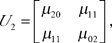
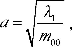
[0058] Merge the paired crater shadow area and bright area, and calculate the combined area m 00 , the central second moment U 2 , U 2 = μ 20 μ 11 μ 11 μ 02 , where μ 20 , μ 11 , μ 02 is a scalar, and is the central second moment U 2 , then the semi-major axis a and semi-minor axis b of the fitting ellipse are respectively

[0059] a ...

specific Embodiment approach 3

[0064] Specific embodiment three: what this embodiment is different from specific embodiment one or two is: utilize Hausdroff distance described in step 6 to realize the matching of crater, concrete steps are as follows:

[0065] Use the i-th row in matrix A and the j-th row in matrix B to find the Hausdroff distance, and use the obtained Hausdorff distance h i,j Use the array H to save it in the corresponding element H(i,j). If the minimum value of the i-th row of the H array is located in the element H(i,j), then the i-th row in the A array and the j-th row in the B array The row has the largest similarity, that is, the crater i in the captured image has the largest similarity with the crater j in the reference image, and the two craters are considered to be successfully matched. Other steps and parameters are the same as those in Embodiment 1 or Embodiment 2.

[0066] Prove the beneficial effect of the present invention by following test:

[0067] A crater matching method...


PUM


Abstract

The invention relates to a meteorite crater matching method based on area ratio, which solves the problems of relatively large rotation of images, mistake matching, mismatching and the like under the conditions of scaling and deformation existing in the existing meteorite crater matching method. The meteorite crater matching method based on area ratio relates to the technical field of image processing, comprising the following steps: selecting out local images in a global image on the surface of a planet as a reference image; then carrying out extraction of meteorite craters on an image shot in landing process based on maximally stable extremal region method; carrying out ellipse fitting on the extracted meteorite craters in the shot image, and calculating the area of fit ellipse; respectively calculating the area ratio between different meteorite craters in the shot image and the area ratio between different meteorite craters in the reference image; and finally utilizing Hausdroff distance as similarity measurement, and matching the meteorite craters detected in the shot image with the meteorite craters in the reference image. The method can efficiently prevent the disadvantages of conventional matching methods, and is an ideal method for carrying out meteorite crater matching in landing process.

Description

technical field [0001] The invention relates to the technical field of image processing, in particular to a crater matching method based on area ratio. Background technique [0002] Landing missions on planetary surfaces require high-precision autonomous navigation systems. Meteor craters are ring-shaped pits formed by small celestial bodies hitting the surface of a planet. They have relatively consistent geometric shapes and clear outlines. Their geometric shapes are less affected by changes in illumination and are easy to match and track as navigation landmarks. In planetary landing missions, craters can be used as navigation landmarks in the planetary landing section to improve the accuracy of the lander's navigation system. [0003] In order to use the global image of the planet’s surface and the crater position data established by pre-in-orbit shooting, it is necessary to match the craters detected in the online image taken during the landing process with the craters i...

Claims


Application Information

Patent Timeline
Patent Type & Authority Applications(China)
IPC IPC(8): G06T7/00
Inventor 徐田来崔祜涛田阳余萌
Owner HARBIN INST OF TECH
Why Eureka
Try Eureka