Supercharge Your Innovation With Domain-Expert AI Agents!

Bracket

A technology of brackets and electromagnets, applied in the field of brackets, can solve problems such as time-consuming, fixed structure cannot be rotated at will, and achieve the effect of preventing small parts from falling off

Inactive Publication Date: 2013-04-03
SHENYANG CHUANGDA TECH TRADE MARKET
View PDF0 Cites 0 Cited by
  • Summary
  • Abstract
  • Description
  • Claims
  • Application Information

AI Technical Summary

Problems solved by technology

[0003] The bracket currently used is a fixed structure and cannot be rotated at will. Therefore, it takes a lot of time for the staff to operate the large-sized parts placed on the bracket. Therefore, the traditional method is not advisable.

Method used


Image

  • Bracket

Examples


Embodiment Construction

[0009] The detailed structure of the present invention is described in conjunction with the accompanying drawings and specific embodiments.

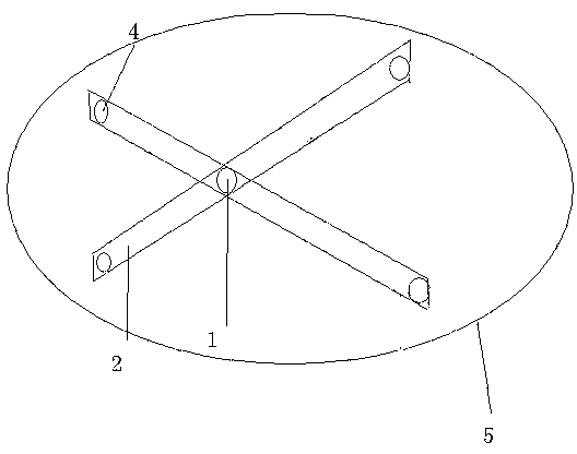
[0010] The bracket is as figure 1 As shown, it includes an electromagnet 1, a beam 2, a wheel 3 and a worktable 4. The connection of the bracket is: two beams 2 cross, and the electromagnet 1 is installed in the turning hole at the intersection, and wheels are installed at both ends of the two beams 2. 3. The upper surfaces of the two beams 2 are installed with the working table 4.

[0011] The working process of this bracket is: this bracket can rotate freely with the intersection point of two beams as the center of circle through the wheels at both ends of the beam, and can make the small pieces on the worktable difficult to fall off by controlling the electromagnet 1.


PUM


Abstract

The invention discloses a bracket, which belongs to the technical field of machinery. The bracket comprises an electromagnet, beams, wheels and a working table top, wherein the bracket is connected in a way that two beams intersect with each other; the electromagnet is arranged in a hole drilled in the intersection of the beams; the wheels are arranged at the two ends of the beams; and the working table top is formed on the upper surfaces of the beams. The bracket has the advantages that the working table top can be rotated optionally, and small parts can be prevented from falling off through the electromagnet.

Description

[0001] technical field [0002] The invention belongs to the technical field of machinery, and in particular relates to a bracket. Background technique [0003] The bracket currently used is a fixed structure and cannot be rotated at will. Therefore, it takes a lot of time for the staff to operate the large-sized parts placed on the bracket. Therefore, the traditional method is not advisable. Contents of the invention [0004] Aiming at the deficiencies in the prior art, the invention provides a bracket. [0005] The technical solution of the present invention is achieved in this way: the bracket includes electromagnets, beams, wheels and worktables, the connection of the bracket is: two beams cross, the electromagnets are installed in the turning holes at the intersection, and the two ends of the two beams Wheels are installed, and worktables are installed on the upper surfaces of the two beams. [0006] The invention has the advantages that: the working surface can b...

Claims


Application Information

Patent Timeline
Patent Type & Authority Applications(China)
IPC IPC(8): F16M11/06F16M11/04
Inventor 李翠
Owner SHENYANG CHUANGDA TECH TRADE MARKET
Features
  • R&D
  • Intellectual Property
  • Life Sciences
  • Materials
  • Tech Scout
  • Unparalleled Data Quality
  • Higher Quality Content
  • 60% Fewer Hallucinations
Learn More