3D (three-dimensional) display control method, control system and display device

A display control method and control method technology, applied to static indicators, optics, instruments, etc., can solve problems such as low brightness, viewing discomfort, large brightness gap, etc., and achieve the effect of avoiding visual discomfort

Inactive Publication Date: 2013-04-03
BOE TECH GRP CO LTD
View PDF5 Cites 2 Cited by
  • Summary
  • Abstract
  • Description
  • Claims
  • Application Information

AI Technical Summary

Problems solved by technology

[0015] However, although the above-mentioned driving method can realize regional control, it will obviously cause the brightness in the 3D region to be very l

Method used


Image

  • 3D (three-dimensional) display control method, control system and display device
  • 3D (three-dimensional) display control method, control system and display device
  • 3D (three-dimensional) display control method, control system and display device

Examples


Embodiment 1

[0058] see Figure 8 As shown in the flow chart, the 3D display control method provided by Embodiment 1 of the present invention includes:

[0059] Step S111, determining the inter-electrode voltage used to drive the display device to display the image so that the transmittance of the 3D area and the 2D area in the display screen meets the preset conditions, including the inter-electrode voltage of the parallax barrier and the inter-electrode voltage of the display panel ; Promptly determine the inter-electrode voltage of the parallax barrier and the inter-electrode voltage of the display panel, so that the transmittance of the 2D area of ​​the parallax barrier is equivalent to the transmittance of the 3D area; the transmittance of the 2D area of ​​the display panel and the 3D area transmittance is equal.

[0060] Specifically, the inter-electrode voltage of the light-transmitting region in the 3D region of the parallax barrier is less than or equal to the threshold voltage, ...

Embodiment 2

[0077] see Figure 10 As shown in the flow chart, the 3D display control method provided by Embodiment 2 of the present invention includes:

[0078]Step S121, determine the inter-electrode voltage of the parallax barrier and the inter-electrode voltage of the display panel, so that the 2D area of ​​the parallax barrier completely transmits light; the transmittance of the 2D area of ​​the display panel is smaller than the transmittance of the 3D area; finally The transmittance of the 2D area and the 3D area in the display screen are equivalent. Specifically:

[0079] Determine the inter-electrode voltage for driving the display device to display the 3D image so that the transmittance of the 3D area and the 2D area in the display screen meets the preset conditions, including the inter-electrode voltage of the parallax barrier and the inter-electrode voltage of the display panel;

[0080] Wherein, the inter-electrode voltage of the light-transmitting region in the 3D area of ​​...


PUM


Abstract

The invention discloses a 3D display control method, a control system and a display device, which are used for displaying 2D (two-dimensional) images in part of an area and 3D images in the other part of the area and preventing finally displayed 3D images from causing the visual discomfort of users due to the great difference between the brightness of the 2D area and the brightness of the 3D area in the process of 3D display control. The 3D display control method provided by the embodiment of the invention includes the following steps: driving parameters for driving the display device to display 3D images, which can ensure that the transmittances of the 3D area and the 2D area in a displayed image can meet a preset condition, are determined, and include driving parameters for a parallax barrier and driving parameters for a display panel; the preset condition ensures that the difference between the transmittances of the 3D area and the 2D area in the displayed image belongs to a preset range; and the driving parameters for the parallax barrier are outputted to a driver for the parallax barrier, and the driving parameters for the display panel are outputted to a driver for the display panel.

Description

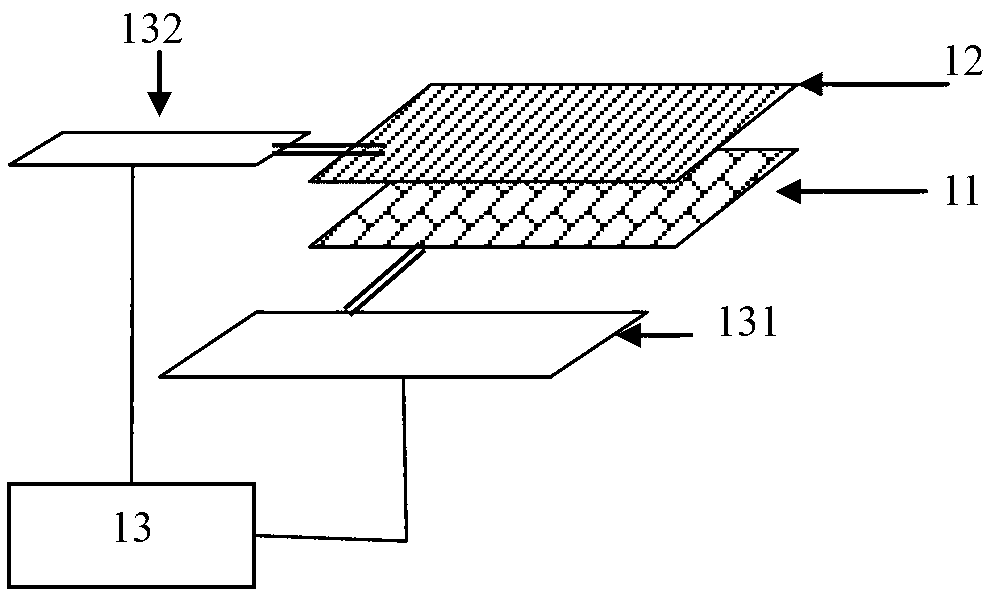
technical field [0001] The present invention relates to the technical field of liquid crystal display, in particular to a 3D display control method, control device and display device. Background technique [0002] The parallax barrier method 3D technology is the most popular 3D display technology now, and the basic structure realized by this technology is as follows: figure 1 As shown, it includes a display panel 11 and a parallax barrier 12 on the light emitting side of the display panel. The parallax barrier is an optical device in which transparent stripes and light-shielding stripes are periodically arranged at intervals. [0003] At present, the parallax barrier method 3D display technology includes an area 3D control method using a parallax barrier, that is, on a screen, a part of the area displays 3D content, and other areas display 2D content. Such as figure 2 As shown, the display device includes the following parts: a display panel 11 , a parallax barrier 12 fo...

Claims


Application Information

Patent Timeline
IPC IPC(8): G02F1/133G02B27/22G09G3/36
Inventor 武延兵
Owner BOE TECH GRP CO LTD
Why Eureka
Try Eureka