Eureka AIR delivers breakthrough ideas for toughest innovation challenges, trusted by R&D personnel around the world.

Tilt offset correction method for actuator

A technology of tilt offset and correction method, applied in the field of optical drives, which can solve problems such as affecting the quality of reading and writing of optical drives, inability to accurately move the control voltage, and crashing the read head.

Inactive Publication Date: 2013-04-03
QUANTA STORAGE INC
View PDF5 Cites 0 Cited by
  • Summary
  • Abstract
  • Description
  • Claims
  • Application Information

AI Technical Summary

Problems solved by technology

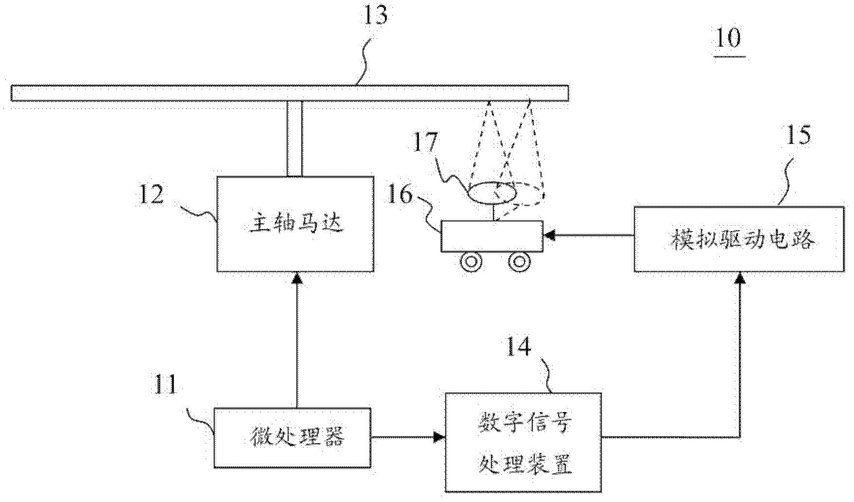
[0004] However, the control voltage output level of the digital signal processing device 14 drives the actuator 16 through the analog drive circuit 15. Due to circuit characteristics such as the impedance of the analog drive circuit 15, there is already a deviation, so that the control voltage cannot accurately move the objective lens 17. to the required position, so as to affect the quality of read and write of the optical drive, or even exceed the maximum allowable movement range and crash the read head
Therefore, the movement offset of the prior art actuator still has the problem of correction to be solved urgently

Method used


Image

  • Tilt offset correction method for actuator
  • Tilt offset correction method for actuator
  • Tilt offset correction method for actuator

Examples


Embodiment Construction

[0020] In order to achieve the above object, the present invention adopts the technical means and its effects, the preferred embodiments are given, and are described as follows in conjunction with the drawings.

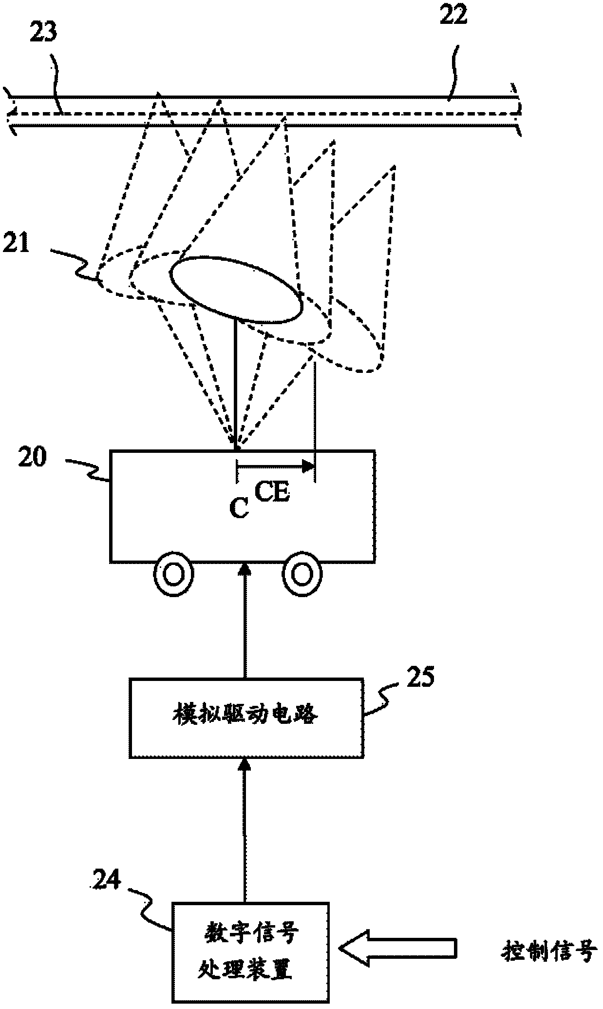
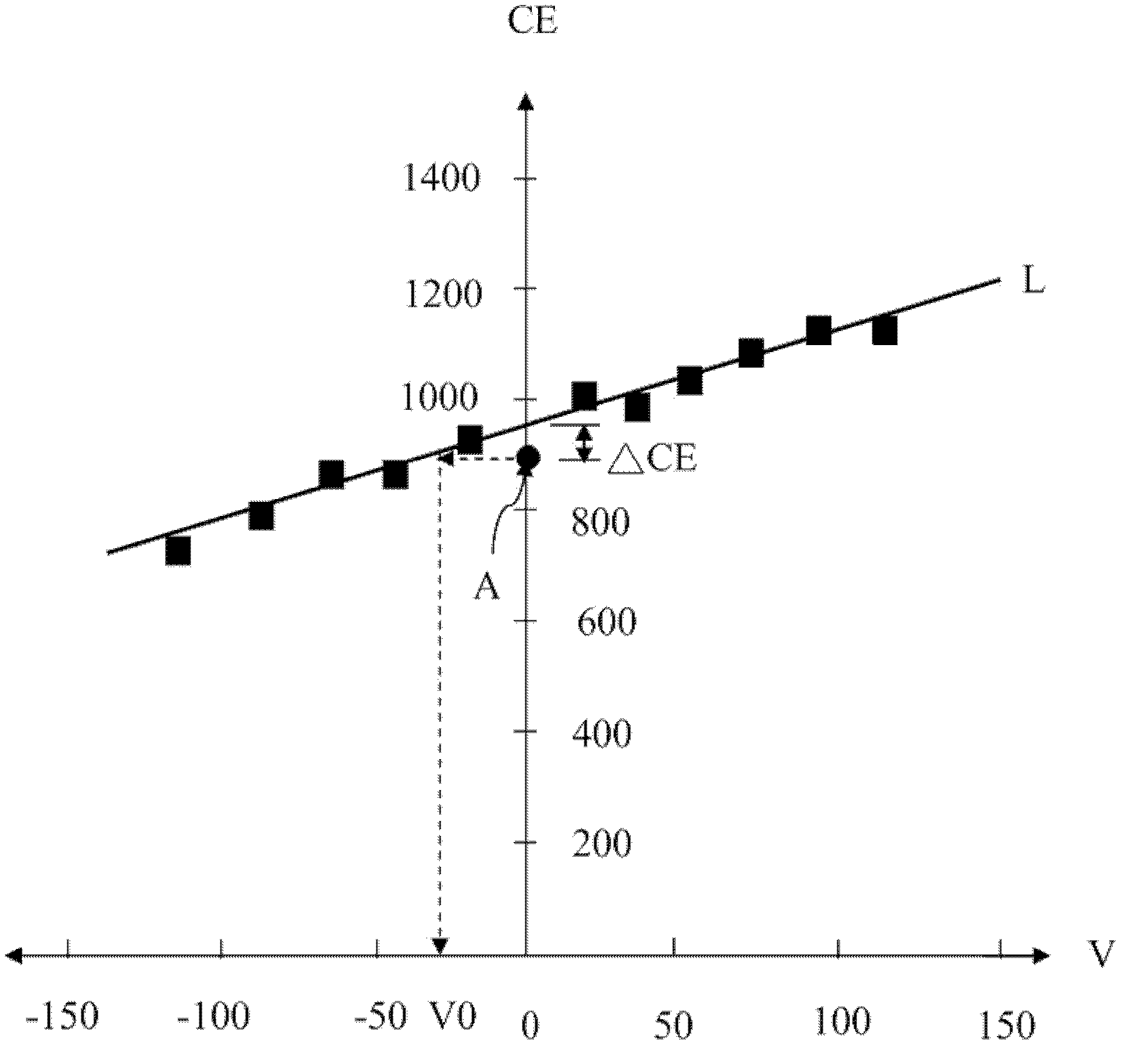
[0021] Please also refer to Figure 2 to Figure 3 , figure 2 It is a functional block diagram of the tilt offset correction of the actuator of the present invention, image 3 It is the approximate offset curve of the present invention. figure 2 Among them, the method for correcting the tilt offset of the actuator 20 in the embodiment of the present invention mainly corrects the tilt offset in the radial direction of the actuator 20. When correcting the tilt offset of the actuator 20, first move the actuator 20 up and down The objective lens 21 focuses the light beam projected by the objective lens 21 on the data layer 23 of the optical disc 22, reducing the interference caused by the actuator 20 driving the objective lens 21 to move up and down. Then output the c...


PUM


Abstract

The invention relates to a tilt offset correction method for an actuator. According to the method, a projection beam is focused at a data layer; a plurality of control voltages are output, an object lens is obliquely moved by an analog driving circuit, and the corresponding displacement signal is recorded; an offset curve is approximated; the zero control voltage is output, the object lens is obliquely moved without the presence of the analog driving circuit, and a reference displacement signal is measured; an offset correction voltage is obtained from the offset curve by using the reference displacement signal; and the tilt offset of the actuator is corrected by compensating the control voltage.

Description

technical field [0001] The invention relates to an optical drive, in particular to a method for correcting the offset generated by the actuator of the pickup head in the optical drive to tilt the objective lens. Background technique [0002] With the popular trend of thinner and smaller consumer electronic products, the optical drive's read head is lightweight, which amplifies the offset of the actuator driving signal, resulting in an increase in the offset of the moving objective lens tilt, which in turn affects the read and write precision of the optical drive. [0003] like figure 1 Shown is a functional block diagram of prior art actuator tilt offset correction. The prior art optical drive 10 uses a microprocessor 11 to control a spindle motor 12 to rotate an optical disc 13 . And control the digital signal processing device (Digital Signal Processor, referred to as DSP) 14, convert the digital control signal into an analog control voltage, and then drive the actuator ...

Claims


Application Information

Patent Timeline
Patent Type & Authority Applications(China)
IPC IPC(8): G11B7/09
Inventor 苏怡宾萧亦隆
Owner QUANTA STORAGE INC
Why Eureka
Eureka Blog
Learn More