
Catch mechanism

A lock and structure technology, applied to furniture parts, household appliances, drawers, etc., can solve the problem of a large number of components, and achieve the effect of reducing the number of components and compact structure

Inactive Publication Date: 2013-04-03
PAUL HETTICH
View PDF3 Cites 7 Cited by
  • Summary
  • Abstract
  • Description
  • Claims
  • Application Information

AI Technical Summary

Problems solved by technology

This locking mechanism has proven to be effective, but it has the disadvantage that a relatively large number of components are required for locking the movable furniture part

Method used


Image

  • Catch mechanism
  • Catch mechanism
  • Catch mechanism

Examples


Embodiment Construction

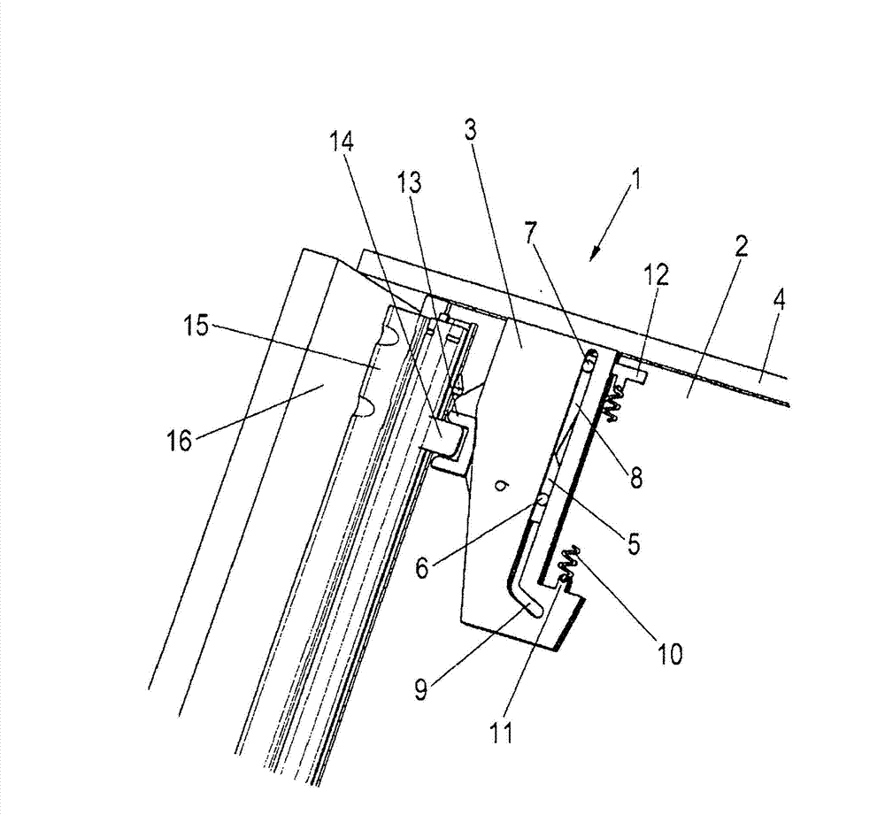
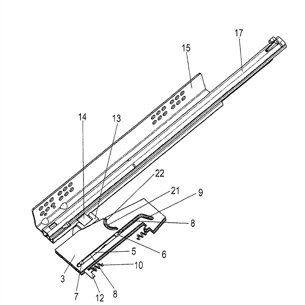
[0021] The latch mechanism 1 is attached to a movable furniture part, for example a drawer 2 , wherein the latch mechanism 1 has a housing 3 which is arranged adjacent to a front panel 4 . Mounted displaceably on the housing 3 is a driver 5 which has a rear pin 6 and a front pin 7 which are held in slot-shaped guide rails. The guide track comprises: a straight section 8 oriented parallel to the direction of movement of the drawer 2 ; and an angled end section 9 inclined or bent relative to the straight section 8 ground setting. When the driver 5 with its rear pin 6 reaches the bent end section 9 of the guide rail, the driver 5 is rotated relative to the housing 3 .

[0022] The driver 5 is prestressed relative to the housing 3 by means of a spring 10 , the spring 10 being held with one end on a boom 11 of the housing 3 and with the opposite end on a boom 12 of the driver 5 .

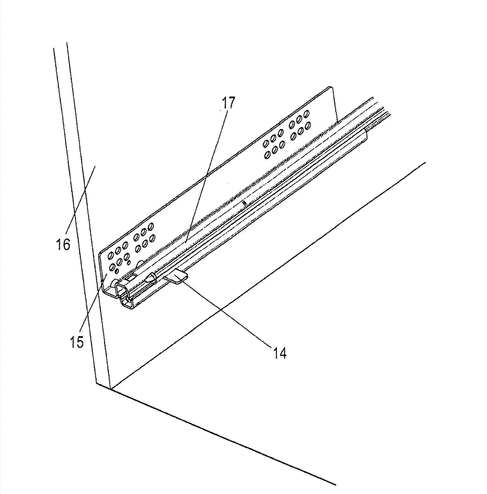
[0023] Furthermore, a U-shaped receptacle 13 is formed on the carrier 5 , into which a projection 1...


PUM


Abstract

The invention relates to a catch mechanism (1), in particular for an ejector device, comprising a housing (3) on which a guideway (8, 9) for a driver (5) is designed, wherein the driver (5) can be displaced along the guideway (8, 9) between two end positions, and the driver (5) is preloaded in an end position, wherein the driver (5) is provided with a curved path (20) for a switch element (21), wherein on a loop-shaped section (25) the curved path (20) comprises a catch depression (23) on which the switch element (21) can be latched against the force of an energy accumulator (10).

Description

technical field [0001] The invention relates to a locking mechanism, in particular to a locking mechanism for an ejection device. The locking mechanism comprises a housing on which a guide track for a driver is formed, wherein the driver can move along The guide rail moves between two end positions and the carrier is prestressed into one end position by a spring. Background technique [0002] DE 20 2009 000 038 discloses a locking mechanism for a pull-out guide, in which an actuator is fastened to the slide rail and engages in a receptacle on the carrier. The carrier is mounted displaceably between two end positions. The driver is connected via a coupling element to a second driver, which can move along a control curve. As a result, the second driver can also lock the first driver in a predetermined position. This locking mechanism has proven effective, but has the disadvantage that a relatively large number of components are required for locking the movable furniture par...

Claims


Application Information

Patent Timeline
Patent Type & Authority Applications(China)
IPC IPC(8): A47B88/04
CPCA47B88/0477A47B88/463
Inventor K·克罗克
Owner PAUL HETTICH
Features
  • Generate Ideas
  • Intellectual Property
  • Life Sciences
  • Materials
  • Tech Scout
  • Unparalleled Data Quality
  • Higher Quality Content
  • 60% Fewer Hallucinations
Learn More